–
Bit 3 is also true, showing that a device
dependent error has occurred.
Use the same technique when you pro
-
gram the enable registers.
–
Select which bits should be true.
–
Convert the binary expression to decimal
data.
–
Send the decimal data to the instrument.
Clearing/Setting all bits
–
You can clear an enable register by pro
-
gramming it to zero. You can set all bits
true in a 16-bit event enable register by
programming it to 32767 (bit 16 not used).
–
You set all bits true in 8-bit registers by
programming them to 255 (Service Re
-
quest Enable and Standard Event Enable.)
n
Using the Queues
The two queues, where the counter stores
output data and error messages, may con
-
tain data or be empty. Both these queues
have their own status bit in the Status
Byte. If this bit is true there is data to be
fetched.
When the controller reads data, it will
also remove the data from the queue. The
queue status bit in the status byte will re
-
main true for as long as the queue holds
6-12 Status Subsystem
Using the Subsystems
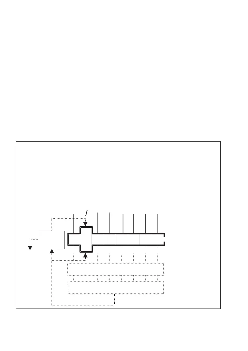
ESB = Event Status Bit
Logical OR
Status Byte
Register
SRQ
signal
OPR = Operation Status Bit
QUE = Questionable Data
EAV = Error Available in the error queue
MAV = Message Available in output queue
16
RQS
MSS
OPR ESB MAV QUE
EAV
DREG0
RQS = Requests Service
MSS = Master Summary Status
Not used
DREG0 = Device Register 0
Service
Request
Generation
Service Request Enable
12481632128
Figure 6-3 The status byte bits.

 Loading...