Input Signaling Conditioning
close to the middle of the signal leads to the
smallest trigger (timing) error since the signal
slope is steepest at the sine wave center, see
Fig. 3-15.
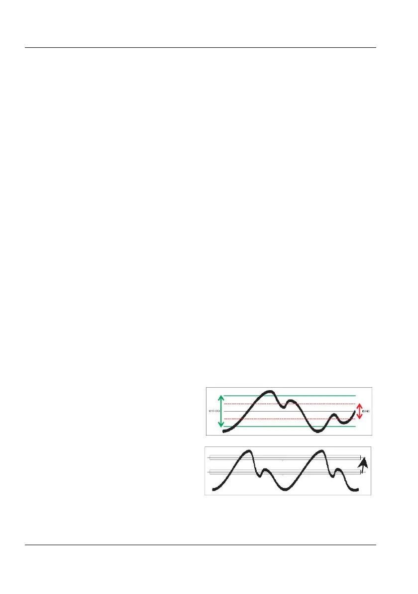
When you have to avoid erroneous counts
due to noisy signals, see Fig. 3-12, expanding
the hysteresis window gives the best result if
you still center the window around the middle
of the input signal. The input signal
excursions beyond the hysteresis band should
For normal frequency measurements, i.e.
without arming, the Auto Trigger function
changes to Auto (Wide) Hysteresis, thus wid-
ening the hysteresis window to lie between
70 % and. 30 % of the peak-to-peak ampli-
tude. This is done with a successive approxi-
mation method, by which the signal's MIN.
and MAX. levels are identified, i.e., the
levels where triggering just stops. After this
MIN./MAX. probing, the counter sets the
trigger levels to the calculated values. The
default relative trigger levels are indicated by
70 % on Input A and 30 % on Input B. These
values can be manually adjusted between 50
% and 100 % on Input A and between 0 %
and 50 % on Input B. The signal, however, is
only applied to one channel.
Before each frequency measurement the
counter repeats this signal probing to identify
new MIN/MAX values. A prerequisite to
enable AUTO triggering is therefore that the
input signal is repetitive, i.e., >100 Hz
(default). Another condition is that the signal
amplitude does not change significantly after
the measurement has started.
NOTE: AUTO trigger limits the maximum measuring
rate when an automatic test system makes
many measurements per second. Here you
can increase the measuring rate by
switching off this probin
g if the signal
amplitude is constant. One single command
and the AUTO trigger function determines the
trigger level once and enters it as a fixed
trigger level.
Switching to Man Trig also means Narrow
Hysteresis at the last Auto Level. Pressing
AUTOSET once starts a single automatic
trigger level calculation (Auto Once). This cal-
culated value, 50 % of the peak-to-peak a
m-
plitude, will be the new fixed trigger level,
from which you can make manual adjustments
if need be.
As rule of thumb, stable readings are free from
noise or interference.
However, stable readings are not necessarily
correct; harmonic distortion can cause errone-
ous yet stable readings.
Sine wave signals with much harmonic distor-
tion, see Fig. 3-17, can be measured correctly
by shifting the trigger point to a suitable level
or by using continuously variable sensitivity,
see Fig. 3-16. You can also use Trigger
Hold-Off, in case the measurement result is not
in line with your expectations.
USER MANUAL ● CNT 9x Series ● Rev.22 February 2020
3-8