Adjustment
86
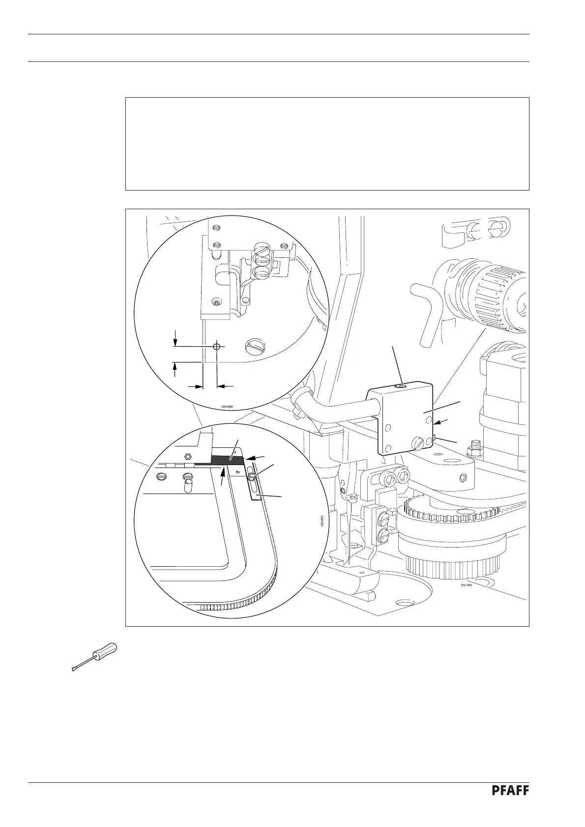
Fig. 12 - 30
12.11 Adjusting the photo sensor and jig stop
Requirement
The scanning point of photo sensor 1 should always be at a distance of 15 mm to the
edge of the needle plate (see enlarged section of the illustration).
Adhesive tape 3 should be attached to the jig in such a way that it is fl ush to the edges
of the jig (see arrows).
The fi rst needle penetration (seam start) should be within the material.
1.
2.
3.
Adjust photo sensor 1 (screw 2) in accordance with requirement 1.
If necessary, correct the position of the adhesive tape 3 in accordance with requirement 2.
Adjust stop 4 (nut 5) in accordance with requirement 3.
Aligning the photo sensor
Bring the sensor to the static teach-in mode by pressing button 6 for approx. 2 seconds
until LED 7 fl ashes green.
Position the jig with adhesive tape 3 under the scanning point of photo sensor 1 and
press button 6 on the sensor for a short time. (ON-position of the sensor)
Remove the jig and press button 6 again for a short time. (OFF-position of the sensor)
●
●
●
●
●
●
1
2
15 mm
15 mm
3
4
5
7
6