input signals. You can open and close individual channels, set scan count
and scan interval, store measurement readings and activate measuring
through channels defined with different measurement functions. The
measurements are taken through all defined channels in sequence. The
scan count limits the total number of measurements the multimeter
makes through all defined channels in one single scanning operation.
The scan interval is the period of time the multimeter waits before it
makes a measurement through the first defined channel. The
configuration set by you is stored in a volatile memory and will be cleared
after the meter is turned off.
※
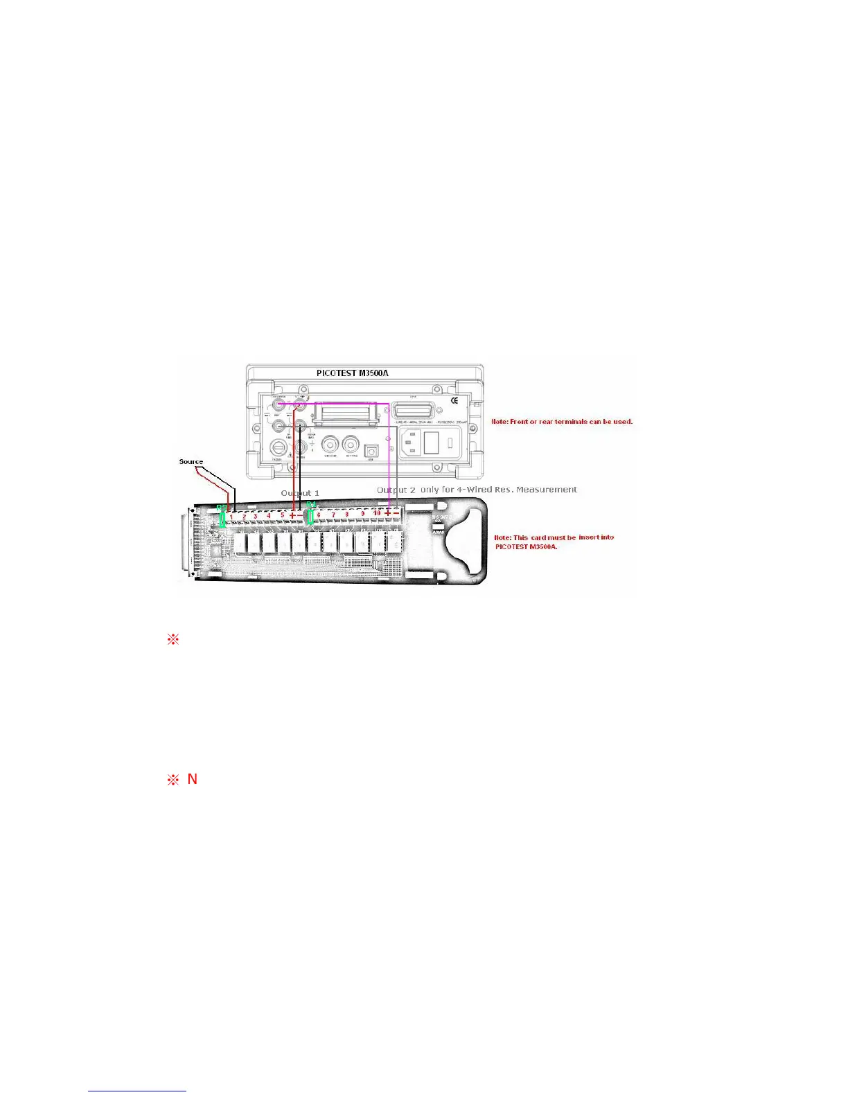
Note: The output 2 is only for 4-wired resistance measurement.
Please refer to the above picture for more connection information. When
you use 4-wired resistance measurement with scanner card, please note
that the channel 1 is relative to the channel 6, channel 2 to channel 7 and
so on.
※
Note: Setting range of scanner card is only limited on DCV, DCI, ACV,
ACI, Frequency, Period and Resistance functions. As to the current
measurements, you can install current shunts on the circuit board R1 and
R2 to allow indirect AC and DC current measurements to be made
through channels 1 and 6 only. At the same time, the DCV and MX+B
functions have to be enabled. For more current measurement via the
scanner card, please refer to “User’s Guide for the Scanner Card”.
Remark 1: In the default situation, current shunts are not installed in