the scanner card.
Remark 2: When the current shunts are installed the channel 1 and
channel 6 will be limited to the current measurement unless you release
the shunts of the R1 and R2.)
※
Note: The Information regarding the Limitation of Input Signals in
Scanner Card is in the following statement.
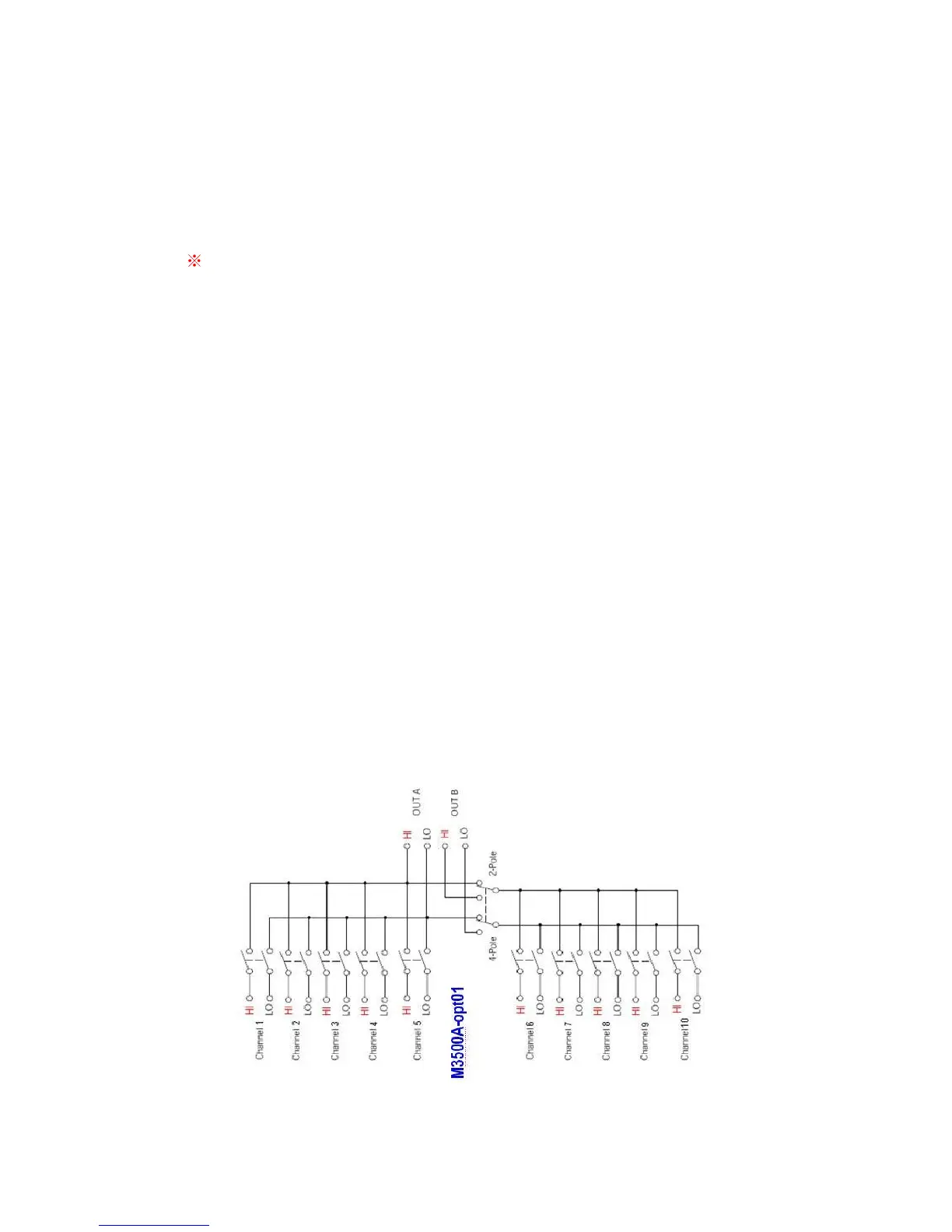
10 Channels: 10 channels of 2-pole relay input. All channels configurable to
4-pole.
CAPABILITIES: Multiplex one of ten 2-pole or one of five 4-pole signals into
DMM.
INPUTS
Maximum Signal Level:
DC Signals: 110V DC, 1A switched, 30VA maximum (resistive load).
AC Signals: 125V AC rms or 175V AC peak, 100kHz maximum, 1A switched,
62.5VA maximum (resistive load).
Contact Life: >100000 operations at maximum signal level; >100000000
operations cold switching.
Contact Resistance: <1ohm at end of contact life.
Actuation Time: 5ms maximum on/off.
Contact Potential: <±500nV typical per contact, 1µV max.
<±500nV typical per contact pair, 1µV max.
Connector Type: Screw terminal, #22 AWG wire size.
Isolation Between Any Two Terminals: >10 Gohm, <75pF.
Isolation Between Any Terminal and Earth: >10 Gohm, <150pF.
Common Mode Voltage: 350V peak between any terminal and earth.
Maximum Voltage Between Any Two Terminals: 200V peak.
Maximum Voltage Between Any Terminal and M3500A Input LO: 200V peak.
ENVIRONMENTAL: Meets all M3500A environmental specifications.
M3500A-opt01 Scanner Card Configuration & Speed List:
Speed of Scanner Card Measurement