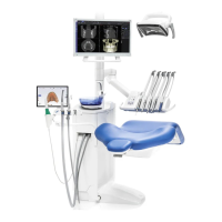
Planmeca Sovereign 15
OPERATIONS PRIOR TO THE CUSPIDOR ATTACHMENT
Installation manual
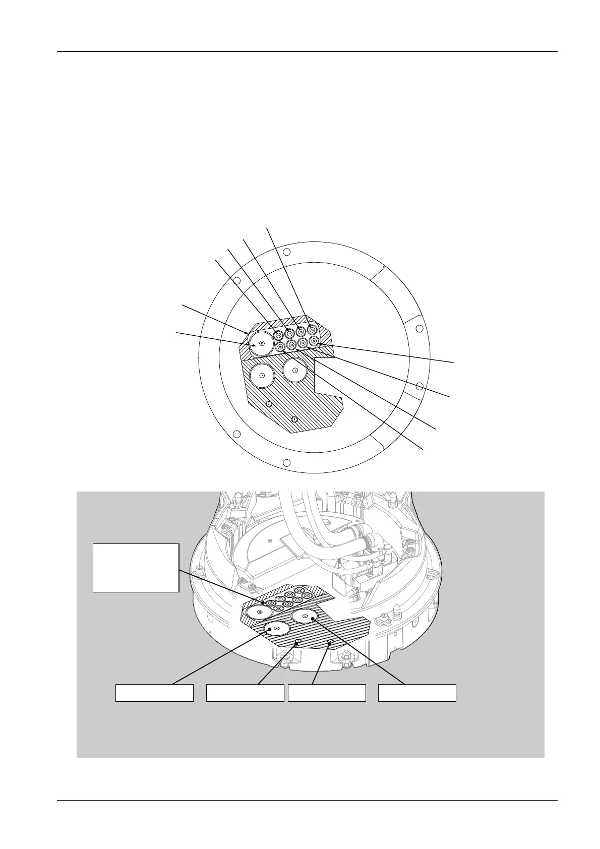
In the case that the optional separate connection case is used, the unit must be positioned so
that the case covers the service tubes coming from the floor into the unit. Attach the cuspidor
to the floor before installing the connection case. For installing the optional connection case
refer to section 7 “INSTALLING THE SEPARATE CONNECTION CASE (OPTIONAL)”.
Cut the water/air and suction/drain tubes that come from the floor so that they extend 25…50
mm (1…2 in.) from the floor. Connect the water/air angle nipples delivered with the unit to the
water and air tubes. Either thread the tubes and screw the angle nipples to the tubes or solder
the angle nipples directly to the tubes. If you screw the angle nipples to the tubes wrap
sealing tape round the threads.
The cables must be located on the electricity and telecommunication area. The drain/suction
tubes as well as air and water tubes must be on the areas marked to the figure shown below.
S6_5.eps
WATER SUPPLYSUCTION LINE DRAIN LINEAIR SUPPLY
Connection area
for electricity and
telecommunication
MAINS SUPPLY 3x2,5mm2 (230V 10A)
Ethernet cable
Dixi cable
Suction motor control cable 2x1.5mm2
VGA cable/ power supply (optional)
Connection area for
electricity and telecommunication
Assistant call/ Door opening
cable 4x0.75mm2
Intra cable
Video cable
Oral X-ray cable
 Loading...