Replacement
Adjustment
4 August 2009
TR-3-37
PCB
3.3 PCB
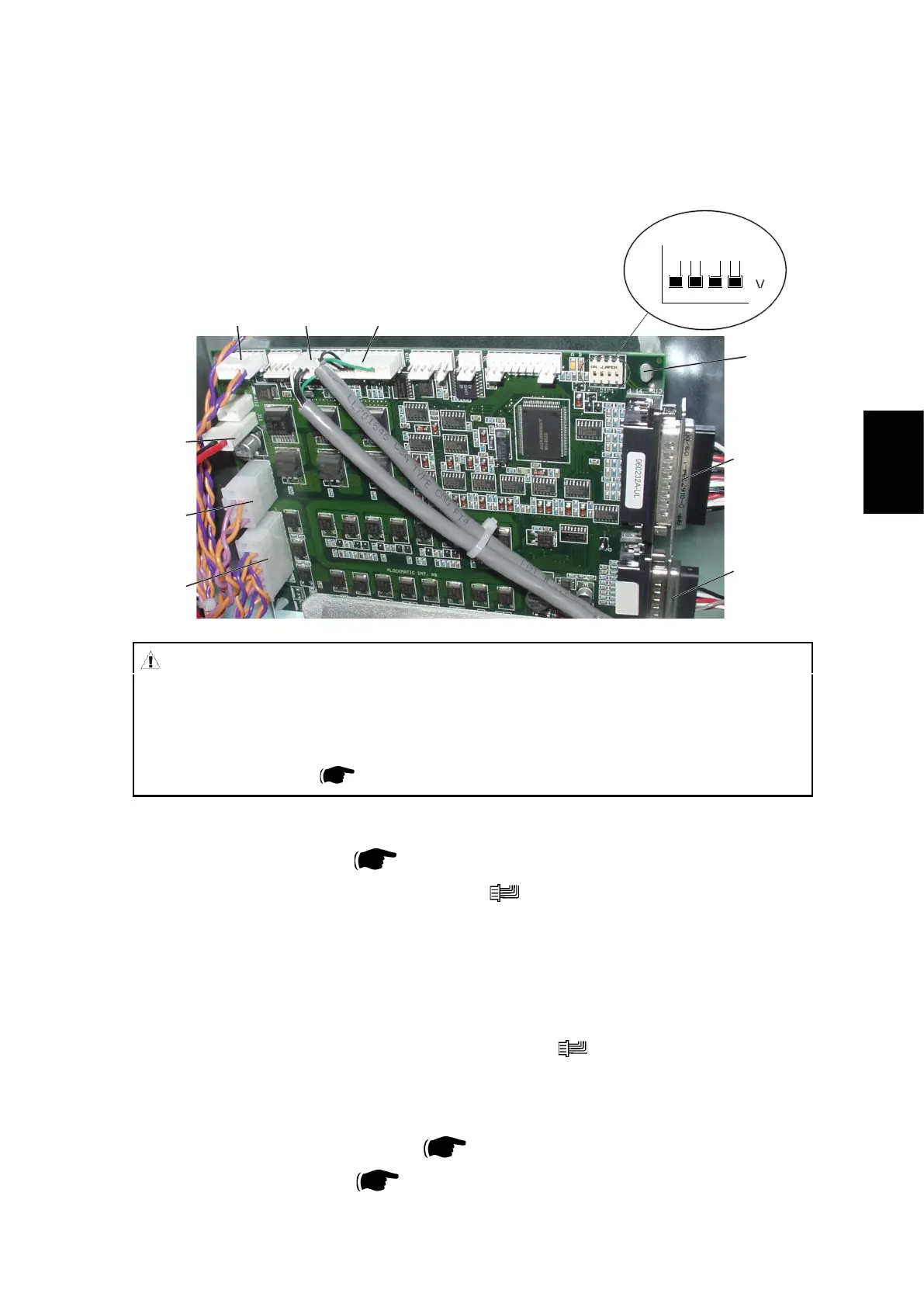
3.3.1 MD6DC PCB ”A”
Removal
1. Remove Rear cover (
3.1.1 ).
2. Remove all connectors from the PCB (
x8 ).
3. Squeeze the barbs of the four pins [A] and lift out the PCB.
Replacement
1. Position the PCB on the pins [A] and snap it in place.
2. Connect all plugs to PCB according to picture (
x8 ).
3. Make sure all DIP-switches are set to OFF according to picture.
NOTE: Make sure replacement PCB has matched software with the system
refering to the latest Technical Bulletin.
Download software if needed ( Service Manual BK5010e 5.2 ).
4. Reinstall Rear cover (
3.1.1 ).
ON
CAUTION
ESD Hazard! ESD (Electrostatic Discharge) can cause software crashes, data and/or com-
munications problems. Failure to use proper ESD procedures will cause damage to elec-
tronic components (example: PCBs). ESD problems can be minimized by maintaining all
machine ground connections, ensuring the proper handling of circuit boards/ sensors
- Use ESD protection when working near PCBs. Failure to use ESD protection is likely to
result in a PCB failure ( Service Manual BK5010e 3.1 ).
A.P6A.P7A.P4
A.P11
A.P3
A.P2
A.P13
A.P14
[A]