3
9929422 R02 - 2017-2019 ACE 900 Service Manual
© Copyright Polaris Industries Inc.
3.39
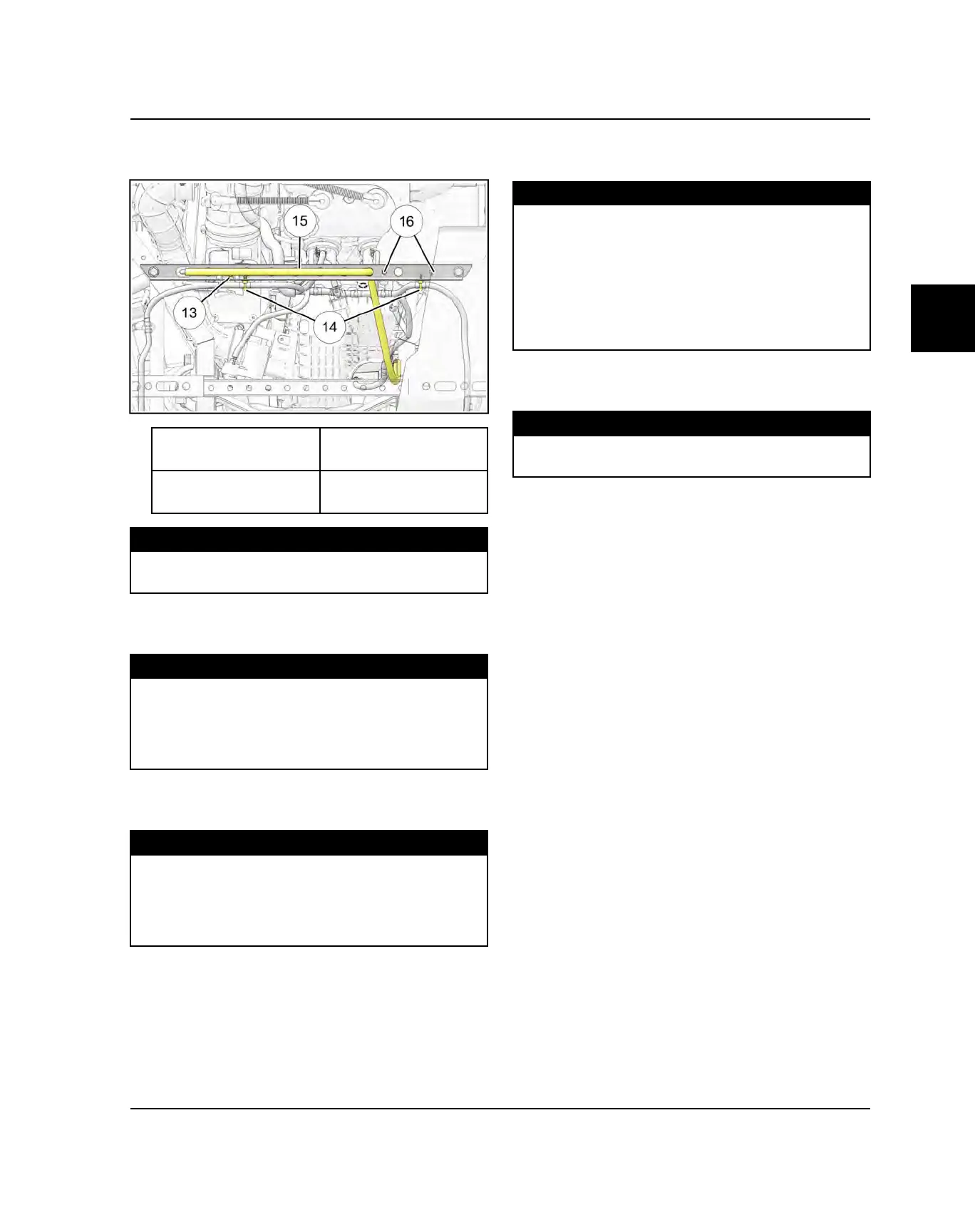
24.Install or connect the following components to the
cargo box brace.
f
Ignition Coil Fastener
h
Transmission Vent
Line
g
Harness Retainers
j
Heat Shield Push
Rivets
TORQUE
Ignition Coil Mounting Bolts:
75 in-lb (9 Nm)
25.Install the rear bumper and cargo box as an
assembly. Torque screws to specification.
TORQUE
Rear Bumper Upper Screws:
14 ft-lbs (19 Nm)
Cargo Box to Frame / Rear Bumper Lower Screws:
8 ft-lbs (11 Nm)
26.Reinstall the rear ROPS tube assembly. Torque
fasteners to specifications.
TORQUE
ROPS Tube Fasteners:
30 ft-lbs (41 Nm)
Side Bolster Screws:
14 ft-lbs (19 Nm)
27.Fill the cooling system with coolant and bleed the
system. See Chapter 3 – Cooling System Bleeding
page
28.If the engine oil was completely drained, add Polaris
PS-4 Synthetic Engine Oil into the crankcase.
FLUID CAPACITY
Recommended Engine Oil:
PS-4 (PN 2876244)
Ambient Temp Range: -35° F to 100° F
PS-4 Extreme Duty (PN 2878920)
Ambient Temp Range: 0° F to 120° F
Capacity: 2.5 qt. (2.4 L)
29.Connect the battery. Torque fasteners to
specification.
TORQUE
Battery Terminal Fasteners:
6 ft-lbs (8 Nm)
30.Install the engine compartment panel and seat.
31.Refer customer to “Engine Break-In Period”
page upon returning vehicle to customer.
ENGINE / COOLING SYSTEM
 Loading...


