8
9929422 R02 - 2017-2019 ACE 900 Service Manual
© Copyright Polaris Industries Inc.
8.27
7. Install wheel and four wheel nuts. Torque wheel nuts
to specification.
TORQUE
Upper Ball Joint Pinch Bolt:
42 ft-lbs (57 Nm)
Lower Ball Joint Nut:
45 ft-lbs (61 Nm)
Front Shock Mounting Bolts:
42 ft-lbs (57 Nm)
Front Caliper Mounting Bolts:
40 ft-lbs (54 Nm)
Wheel Nuts (Alum):
30 ft-lbs + 90° (41 Nm)
Lower Ball Joint Removal
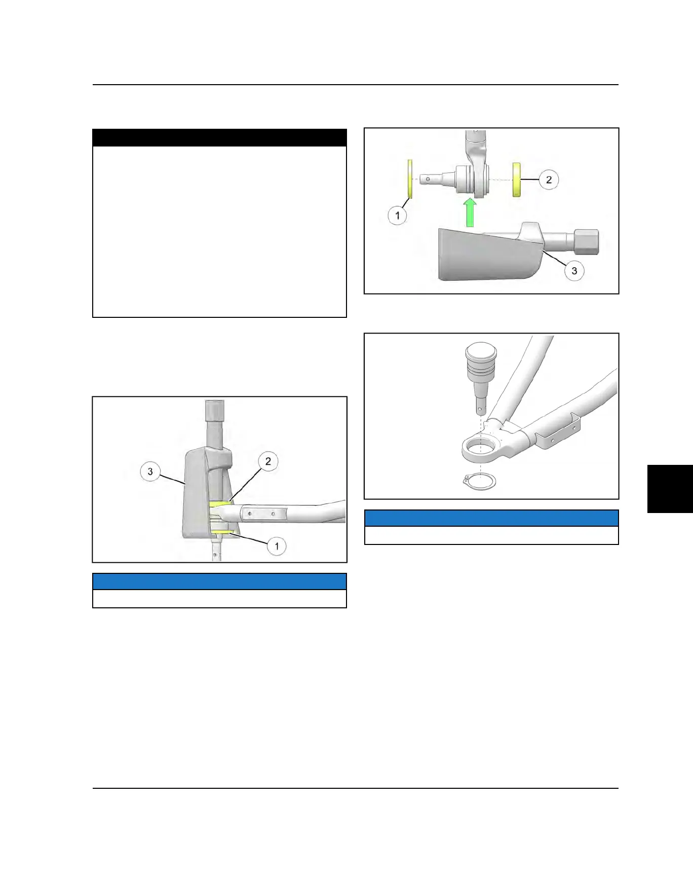
1. By hand, install the NEW ball joint into the A-arm.
2. Using PU-50506, position the Installation Adapter
w
over the face of the ball joint.
NOTE
Image for reference only.
3. Position the Spacer
q
over the shaft of the ball joint
so it is against the A-arm.
4. Install the Press Asm.
e
onto the A-arm to engage
the Installation Adapter and Spacer.
5. Tighten the Press Asm. screw and fully install the ball
joint into the arm.
6. After the new ball joint is fully installed into the A-arm,
install a new retaining ring.
NOTE
Image for reference only.
7. Repeat the ball joint service procedure for any
additional A-arm ball joint replacements.
8. Reverse the Service Preparation procedures for
installation.
9. Torque all fasteners to Specification.
STEERING / SUSPENSION
 Loading...