Using Events, Logic, And IR
9 - 21
The value of a logic input array is read with the digital_gpio_value parameter.
If a logic pin is part of an array, it may not also be used as an individual logic
input pin.
Logic output arrays may also be defined. The value of a logic output array is
set using the digital_gpio_value parameter. For example if three logic output
pins are part of a logic output array, the command
set digital_gpio_value “Output Array” 7
will set all of the pins in the array named “Output Array” to the value 1.
LED Example
The following figure is an example of how to use an external LED. Most stan-
dard LEDs require approximately 2.0 V to illuminate. In this example a 274
ohm resistor is used to limit the current from the 5V supply of Pin 1and to limit
the voltage and current to a safe level for the LED. Increasing the series resis-
tor value will decrease the current through the circuit and will also decrease
the voltage at the input to the LED, reducing the brightness of the LED.
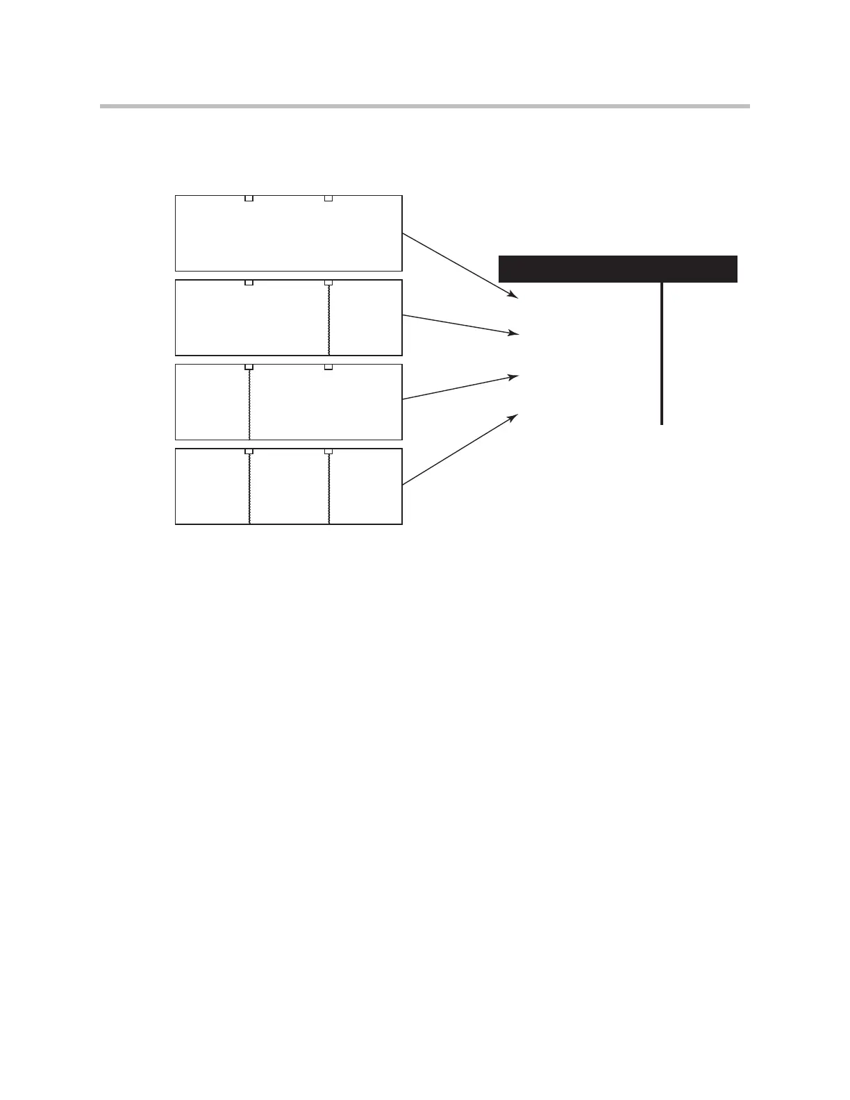
Room 1 Room 2 Room 3
Switch 2 Switch 1
Room 1 Room 2 Room 3
Switch 2 Switch 1
Room 1 Room 2 Room 3
Switch 2 Switch 1
Room 1 Room 2 Room 3
Switch 2 Switch 1
TwoPinArray[2] TwoPinArray[1] Value
1 1 3
1 0 2
0 1 1
0 0 0
1 = Switch Open (wall open)
0 = Switch Closed (wall closed)