Design Guide for the Polycom SoundStructure C16, C12, C8, and SR12
14 - 6
reduce room gain by lowering the audio amplifier level and increasing the
input gain on the remote audio coming into the SoundStructure to ensure the
signal levels are at a reasonable level.
If the reference is set properly and includes all the remote audio sources and
there is still an echo heard by the remote participants, the next step is to under-
stand how the amplifier output fader is set.
In some applications, the line level outputs of the SoundStructure could be
connected to the inputs of a microphone-only device that requires the outputs
of the SoundStructure to be attenuated significantly to be compatible with the
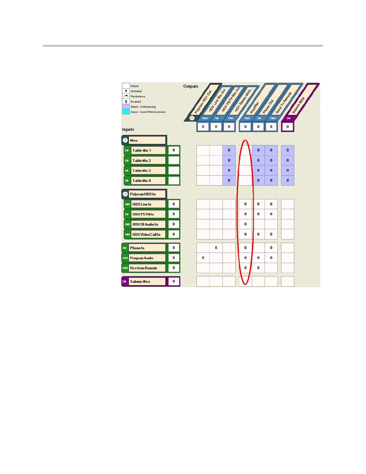
microphone level inputs. If the output fader on the amplifier channel is used
to attenuate the amplifier signal as shown in the figure below and the AEC ref-
erence is also set to the amplifier output, then the AEC reference would also be
attenuated by the fader amount.