© 2017 PoolPak LLC. All rights reserved. MPK Series - Installation, Operation and Maintenance | 51
PoolPak
®
MPK Series IOM
CPCS Controller Features
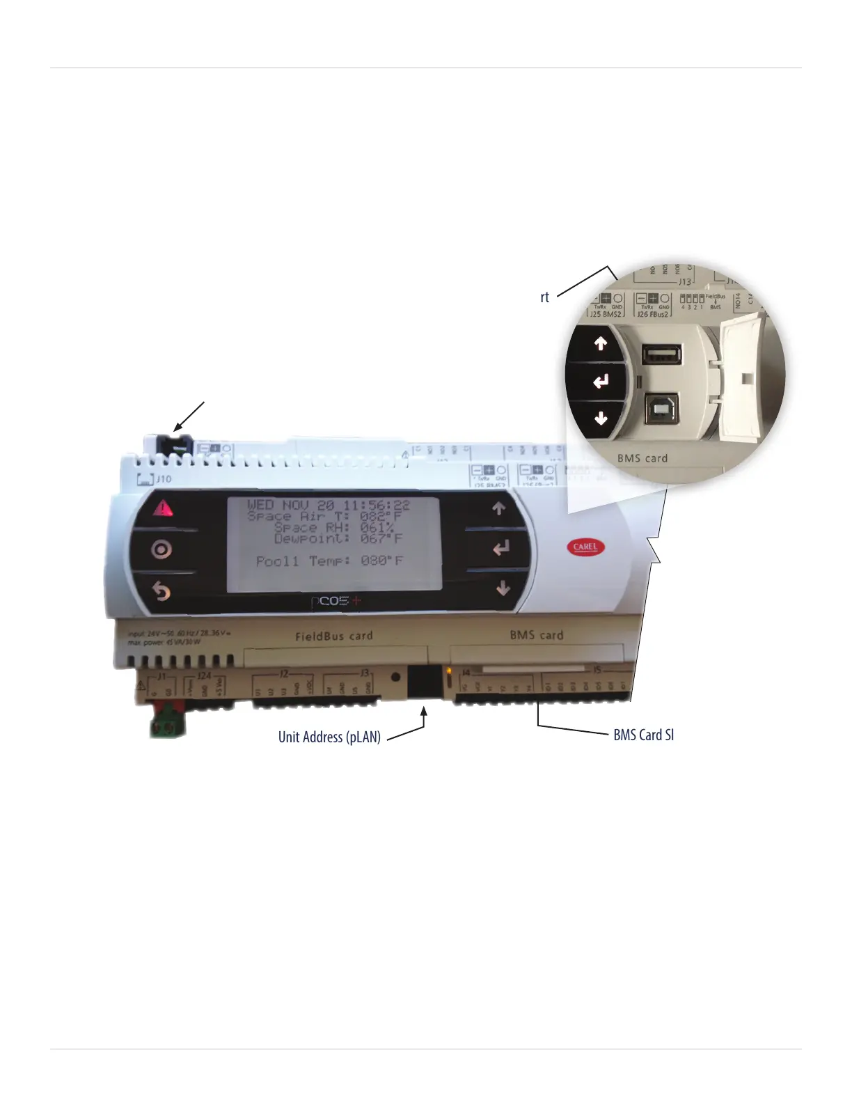
The CPCS Controller (Figure 5-2) consists of several Control Modules (CM). The main controller, named Control
Module 1 (CM1), is the only controller in the main control cabinet with a display. The CM1 display has the
same keys and can be operated in the same way as the remote keypad. See the picture showing the physical
characteristics and feature call outs of the CM1.
In addition to the key features for the RIU, more description of some of the physical features on the CM1 controller
is below:
• RIU/Keypad connection (J10): For service convenience, there is an auxiliary RJ25 jack located on the upper left
side of CPCS Control Module #1, port J10. The RIU may be removed from its remote location and connected
here using the special RJ-25 cable supplied with the control system.
• USB port: For communication with standard USB pendrives or direct connection to a PC, this port is used
primarily for downloading fault history logs and other system performance parameters.
• BMS card slot: This slot is the connection point for the Building Automation System to the CPCS Controller.
See the Communications section for more details.
• Unit Address (pLAN): This feature is for adjusting the controller address and is used specifically
for CPCS Network Operation.
Figure 5-2. CPCS Controller (CM1) Display
RIU/Keypad Connection (J10)
Unit Address (pLAN)
BMS Card Slot
USB Port