© 2017 PoolPak LLC. All rights reserved. MPK Series - Installation, Operation and Maintenance | 65
PoolPak
®
MPK Series IOM
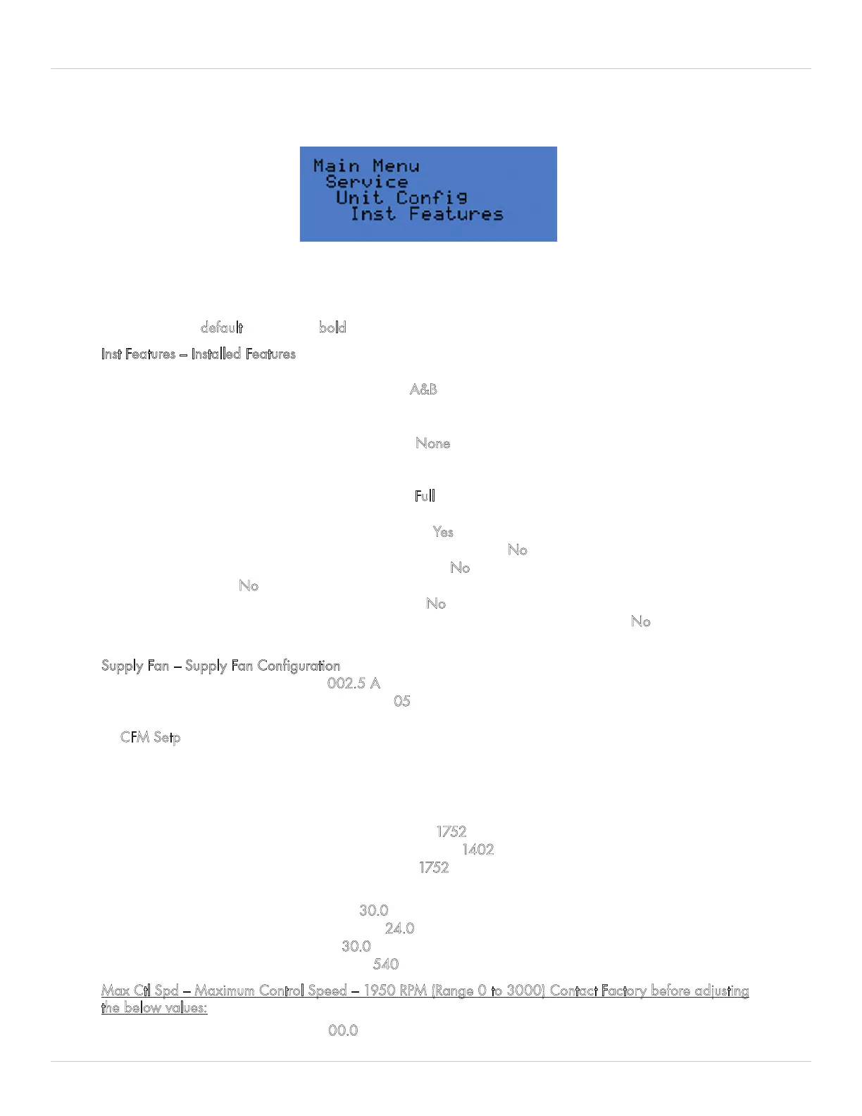
Figure 5-23. Unit Configuration - Installed Features Menu
The Unit Configuration menu is where to access system set-up parameters. From here, the following configuration
parameters can be accessed: Installed Features, Supply Fan, Exhaust Fan, Purge Fan, Compressor System, Dampers,
Pool Water Heating, Auxiliary Air Heating System, Auxiliary Air Cooling System, Auxiliary Air Dehumidification
System, Space Temperature Control, Space Dewpoint Control, Mixing Box Control, and BAS Interface. For all below
parameters, the default setting is in bold font.
Inst Features – Installed Features
• Cpr Stgs Ins – Compressor Stages Installed – 3 (Range 0 to 4)
• Cpr1 Wtr Circ – Compressor 1 Water Circuit – A&B (Range A or A&B)
• Cpr2 Wtr Circ – Compressor 2 Water Circuit – A (Range A or B)
• Split Wtr Cond – Split Water Condenser – No or Yes
• Air Cool Type – Mechanical Air Cooling Type – None, ACC (Air-Cooled Condenser),
WCC (Water Cooled Condenser, or CHW (Chilled Water Coil)
• Max EF Vol – Maximum Exhaust Fan Volume – 32.6 kCFM (Range 0 to 99.9)
• Pool Wtr Cond – Pool Water Condenser Type – Full or Partial or None.
• Exhaust Fan Inst – Exhaust Fan Installed in unit – No or Yes
• Purge Fan Inst – Purge Fan Installed in unit – No or Yes
• Spc Press Sen Inst – Space Pressure Sensor Installed in space – No or Yes
• Rtn CO2 Sen Inst – Return Air CO2 Sensor Installed – No or Yes
• MultiUnit Control – No, set to Yes for multi-unit networking
• Rem Exh Fan Ins – Remote Exhaust Fan Installed – No or Yes
• CW/HW DH Mode – Chilled Water/Hot Water Dehumidification Mode installed – No or Yes
• Fan Speed Ctl Type - EC or VFD
Supply Fan – Supply Fan Configuration
• Run Cur Tol – Fan Proof Current – 002.5 A (Range 0 to 999.9) D cabinet only
• Run Cur Dly – Time Delay to Prove Current – 05 s (Range 0 to 99) D cabinet only
• Flow Ctl – Airflow Control Mode
• CFM Setp – This mode indicates that the fan speed or outside air damper position will be controlled to maintain
airflow at CFM set points.
• Spd Setp – This mode indicates that the supply fan speed will be controlled by setting the supply fan
RPM set points.
If Spd Setp selected, set the below setpoints:
• Occ Speed – Fan Speed during Occupied Mode – 1752 RPM (Range 30 to 1800)
• Unocc Speed – Fan Speed during Unoccupied Mode – 1402 RPM (Range 30 to 1800)
• Purge Speed – Fan Speed during Purge Mode – 1752 RPM (Range 30 to 1800)
If CFM Setp selected, set the below setpoints:
• Occ Flow – Occupied Mode Airflow – 30.0 kCFM (Range 0 to 70)
• Unocc Flow – Unoccupied Mode Airflow – 24.0 kCFM (Range 0 to 70)
• Purge Flow – Purge Mode Airflow – 30.0 kCFM (Range 0 to 70)
• Min Ctl Spd – Minimum Control Speed – 540 RPM (Range 0 to 2000)
Max Ctl Spd – Maximum Control Speed – 1950 RPM (Range 0 to 3000) Contact Factory before adjusting
the below values:
• Ctl Dband – Control Deadband – 00.0 kCFM (Range 0 to 10.0)
Unit Configuration