JETSTREAM
1.0:E15
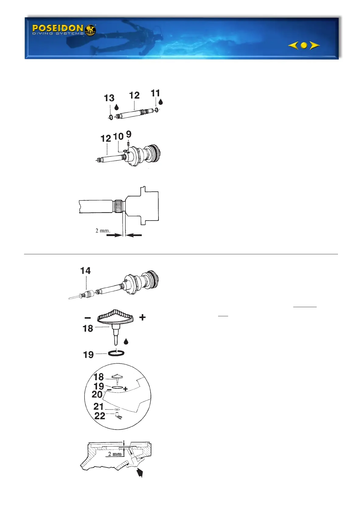
5. Install the o-rings (11,13) on the
valve tube (12). Grease the threads
and the o-rings.
6. Screw in the valve tube (12) until
about 2 mm space remains as
illustrated.
7. Install the rubber plate (10). Screw in
the set screw (9). Do not tighten up.
8. Screw the servo valve (14 ) on to
valve tube (12). Tighten up. Be
careful not to bend the valve needle.
9. Test the low pressure valve for
leakage. See chapter: Final
adjustment.
SWITCH
1. Fit in o-ring (19) and lubricate it.
2. Fit in the switch with the narrow
part against the - minus sign on the
second stage valve. See diagram.
3. Install the locking washer (21) on
the switch (18). Press it on a drift.
Tighten the locking washer so that
there is sufficient resistance when
setting the switch.
4. Fix the diaphragm cam (22) upon the
switch (18). Set switch at - (minus),
press the diaphragm cam into
correct position per the diagram.
The distance from the top of the
diaphragm cam to the housing should
be 2 mm, concerns diaphragm of
silicone rubber, see diagram. Carefully
push diaphragm cam into the right
position. Note the cam should be
pushed slowly on to the switch so that
the switch is not moved.