Section V Parameter Function Table
98
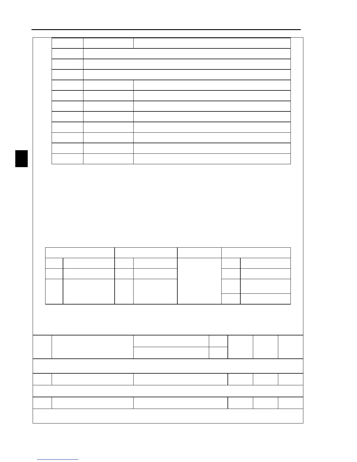
Inverter output phase-lost
RS485 communication terminal A failure
RS485 communication terminal B failure
Parameter identification problems
1 : Set frequency at the time of fault
The output frequency of the inverter at the time of fault
2 : Output frequency at the time of fault
The output frequency of the inverter at the time of fault
3 : Output current at the time of fault
The actual output current at the time of fault
4 : Output DC voltage at the time of fault
The actual output voltage at the time of fault
5 : Running state at the time of fault
The running state at the time of fault
LEDdisplay is below:
6 : Running time at the time of fault
The running time at the time of fault
7 : Inverter IGBT temperature at the time of fault
Inverter IGBT temperat
0 : No action, the fault records retains
1 : The fault records resets
Inverter rated output current
The rated input voltage of the inverter. It would be set as per inverter input voltage level
before leaving factory.

 Loading...
