IV-1-2. E00=13: Voltage regulation power
In this mode,connect AI2,AI3 to Hall,then measure the output voltage and use2Halls to do
redundant work to ensure the output voltage will not exceed the Hall voltage limitation.
In this mode, the following parameters should be adjusted:
PID function group, P02 PID feedback signal selection.
AI2 is detected by analog and AI3 works as a redundant configuration to ensure the output
voltage safe and reliable.
When Feedback voltage is 100%, the corresponding Hall voltage is 500VAC, Hall output
voltage is 5V.
Set o03=50%, o05=50%.
P03 PID given signal selection, you can set through the keyboard, analog AI2, pulse and other
means to set a given voltage.
Given voltage is calculates as follows:
When the given voltage =220VAC, given voltage setting =220*1.414/500*100%=62.2%
Other PID parameters are adjusted according to the site.
Under PID regulated power supply mode, the voltage acceleration and deceleration time is
controlled by PID parameters, it won‟t affect by voltage acceleration and deceleration time.
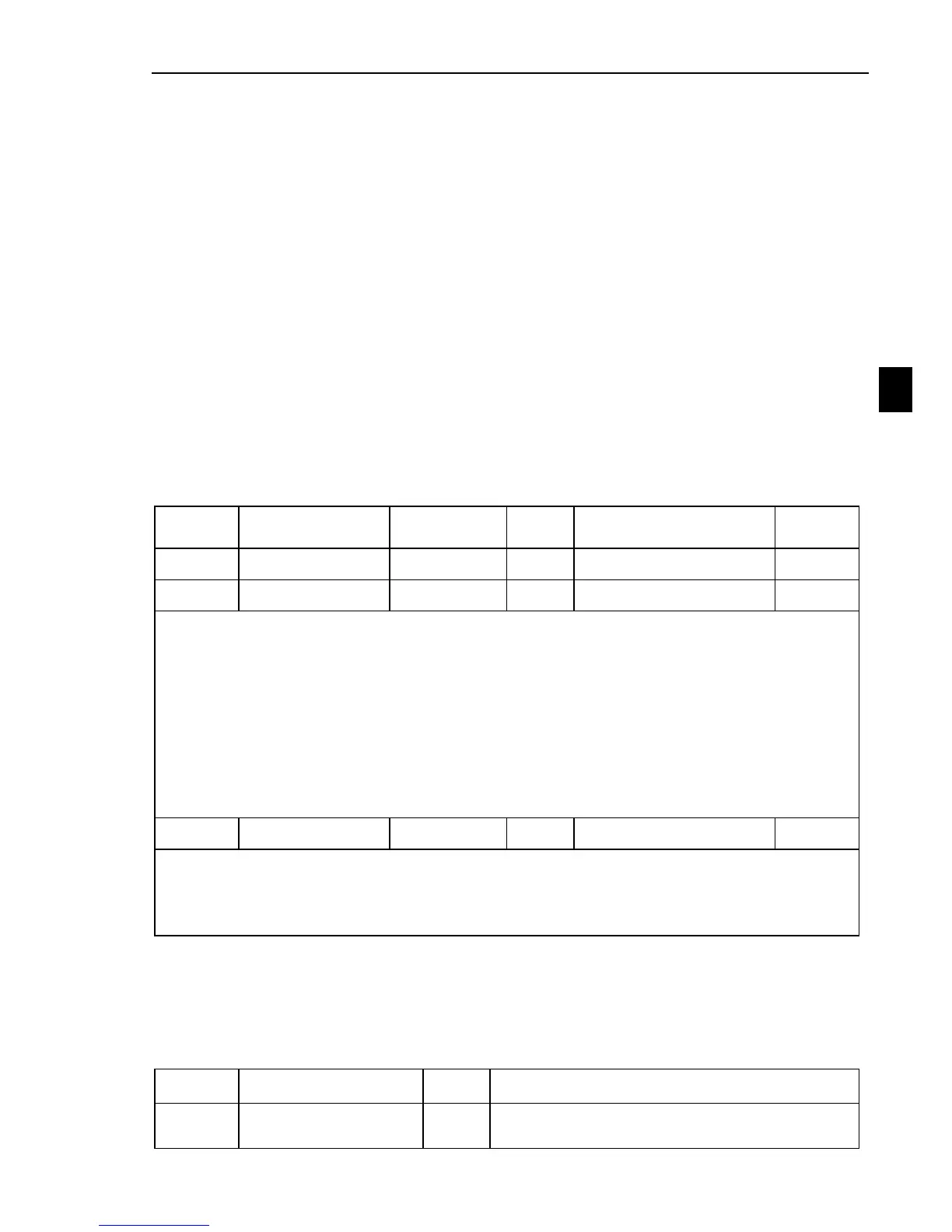
Voltage regulation power specific parameters:
In Voltage regulation power mode, the output and input voltage are both adjustable.
The increasing time and decreasing time of output voltage is adjusted by F09 and F10.
E16 is the voltage increasing time, the definition of the output voltage increasing time is
from 9999 corresponds to 999.9 seconds.
E17 is the voltage decreasing time, the definition of the output voltage decreasing time is
from 9999 corresponds to 999.9 seconds.
Voltage increasing/decreasing time just used to adjust the accelerate/decelerate time of
output frequency when the inverter running.
After the stopping command sent, the controller will stop the frequency output when the
output frequency decelerate to 0 hz.
For safety and reliability to ensure that the output voltage to bear the load within
system,we need to define the maximum output voltage of the system.
If the System highest withstand voltage 250VAC;
Then E18=250VAC.
IV-2. Converter water supply controller instruction
IV-2-1. Constant water supply system parameters:
1、 loading types with constant water supply function:

 Loading...
