Section II Installtion & Standby Circuit
5
2-4. Main Circuit Terminals (G Series)
2-4-1. PI8600 Main Circuit Terminals
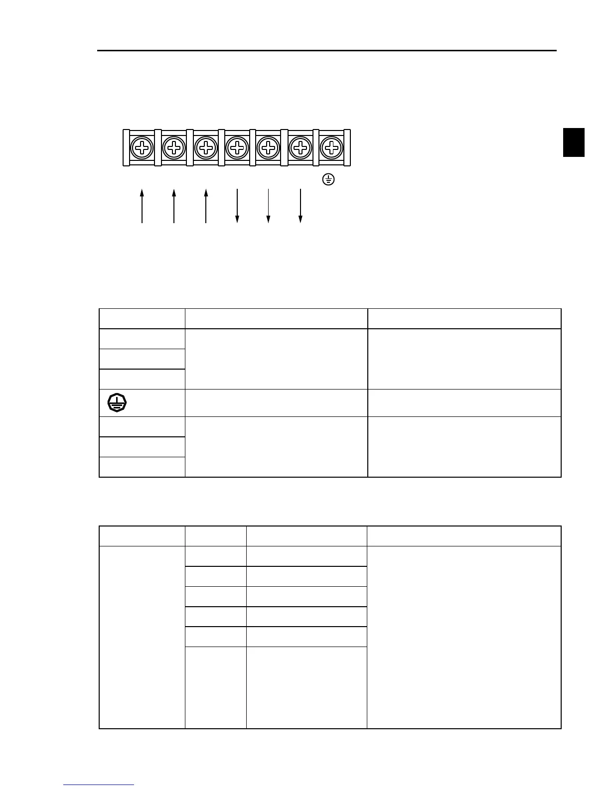
1.Main Circuit Terminals
W/T3V/T2U/T1
T/L3
R/L1
S/L2
/E
AC Input Line
Terminals
Motor connection
Note: Single phase inverter hasn‟t S input terminal
The above kW categaries are for G type inverter.
2-4-2. Terminal Function
Power input for frequency inverter
Connected to 3-phase power,
(Single input connected to R, T)
Power output for frequency inverter
Connected to 3-phase motor
2-5. Control Circuit Terminals
2-5-1. Control Circuit Terminals
Multi-functions input terminal. For
details Please read o36~o46.
Enter a valid polarity can be controlled
by o47.
DI1~DI4 Drive model can be controlled
by JP4.
Above 11kW:
DI5~DI6Drive model can be controlled
by PLC output terminal .
Below 11kW:
DI5~DI6Drive model can be controlled
by PLC output terminal .

 Loading...
