955725_4
41
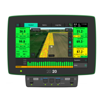
Select the appropriate number of ranks under the
Frame Type. This defines what measurements
can be entered in the Air Seeder Measurements
tab.
The rest of the Air Seeder specs, such as row number and spacing, are under the Air Seeder
Details (Tab 5).
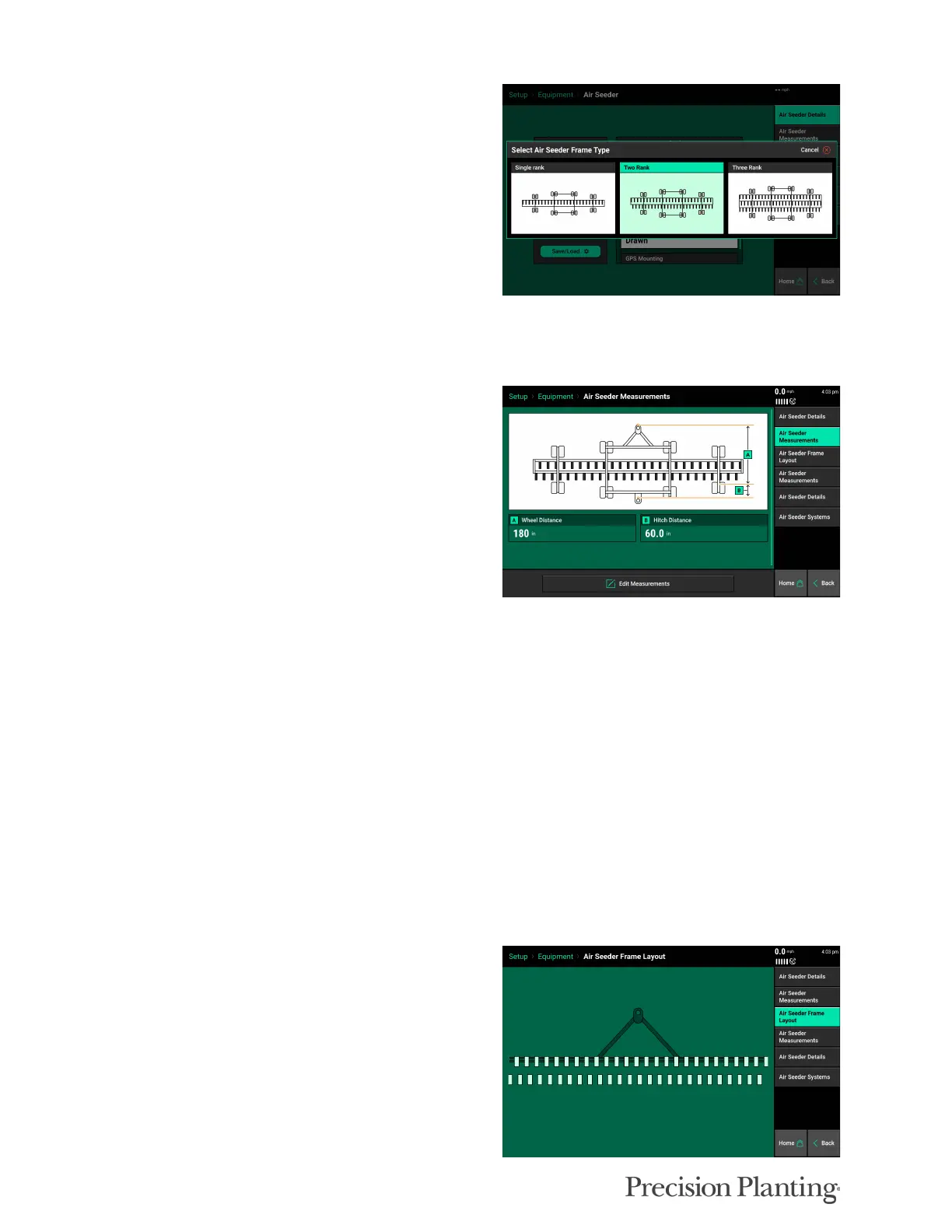
AIR SEEDER MEASUREMENTS (Tab 2)
Select “Air Seeder Measurements” to set up the
GPS measurements for the air seeder. GPS offset
measurements must be set up prior to planting in
order for the monitor to correctly control and
model the air seeder.
The Air Seeder Measurements Tab 2 sets the measurements for the Air Seeder frame ( wheel and
hitch distance), and the Air Seeder Measurements Tab 4 sets the measurements for the Ranks
(seed exit and offsets).
To edit the measurements, select the Edit Measurements option. Enter the appropriate wheel
distance, and select next. Enter the appropriate Hitch distance and select Done.
A — Wheel Distance
Enter the distance from the pivot point to the center of the rear frame wheel axle.
B — Hitch Distance (Tow-behind cart systems only)
Enter the distance from the center of the rear frame wheel axle to the center of the rear hitch
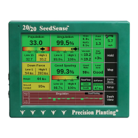
AIR SEEDER FRAME LAYOUT (Tab 3)
The frame layout page shows a visual
representation of the measurements. This frame
diagram should match how the air seeder
physically looks. If this diagram does not match
the seeder’s actual layout, adjust the air seeder
measurements as needed.