955725_4
42
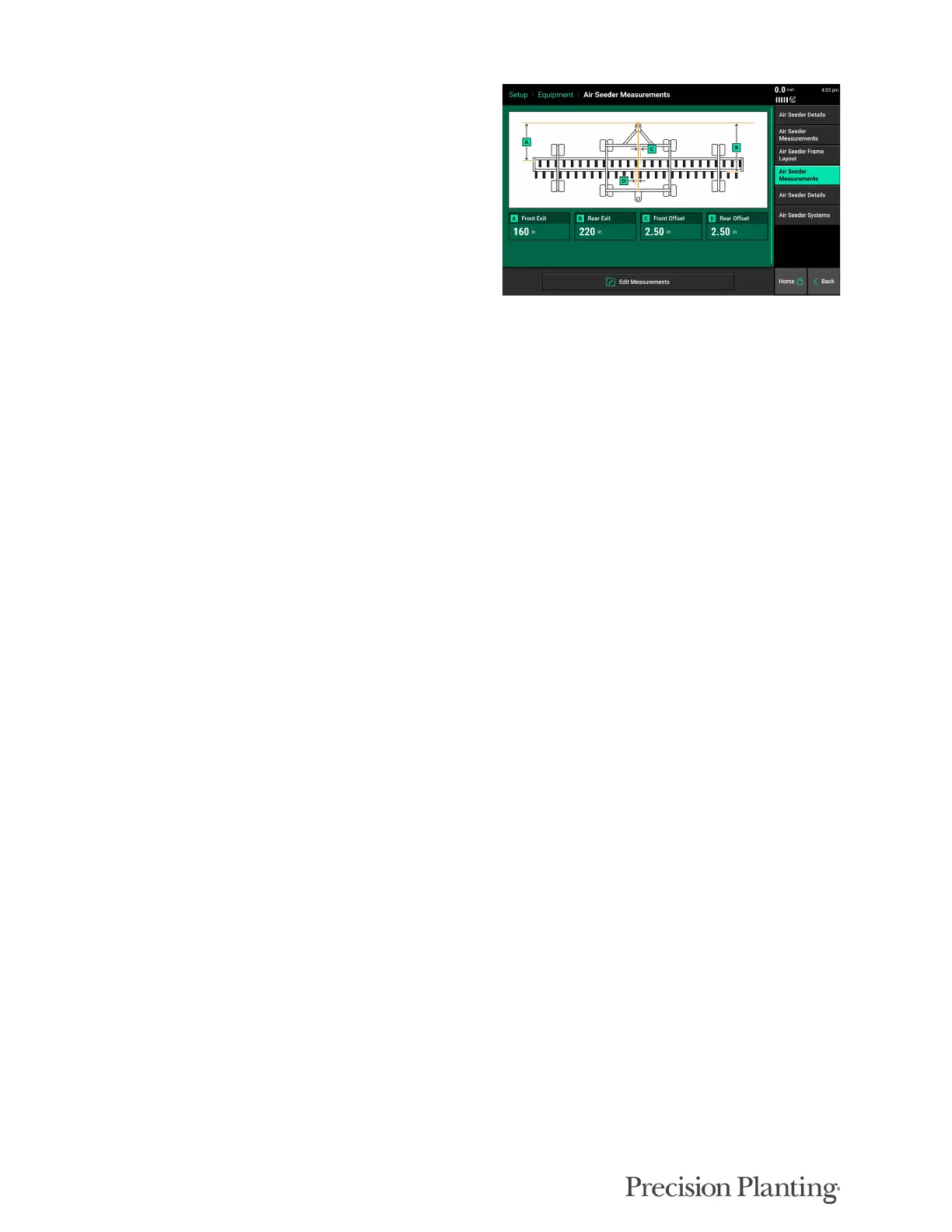
AIR SEEDER MEASUREMENTS (Tab 4)
The Air Seeder Measurements Tab 2 sets the
measurements for the Air Seeder frame ( wheel
and hitch distance), and the Air Seeder
Measurements Tab 4 sets the measurements for
the Ranks (seed exit and offsets).
Depending on how many seeding ranks are
selected, two to four different measurements will
need to be entered into the system.
A — Front Seeding Rank Seed Exit
Enter the distance from the pivot point to the seed tube exit for the front rows. Then select the
active rows for the Front Seeding Rank.
B — Rear Seeding Rank Seed Exit
Enter the distance from the pivot point to the seed tube exit for the rear rows. Then select the
active rows for the Rear Seeding Rank.
C — Front Seeding Rank Offset From Center
The left/right offset of the forward most seeding rank must be entered. This is the distance from
the centerline of the tractor to the center of the front seeding rank. Enter this distance into Box D.
Select “Measure from left” if the rows are offset to the left side of the centerline of the tractor and
“Measure from right” if the rows are offset to the right side of the centerline of the tractor.
D — Rear Seeding Rank Offset From Center
The left/right offset of the rear most seeding rank must be entered. This is the distance from the
centerline of the tractor to the center of the rear seeding rank. Enter this distance into Box E.
Select “Measure from left” if the rows are offset to the left side of the centerline of the tractor and
“Measure from right” if the rows are offset to the right side of the centerline of the tractor.
If the Air Seeder Profile has Seeding Ranks and Fertilizer Ranks, repeat the same steps above for
Fertilizer Rank Measurements.