955725_4
47
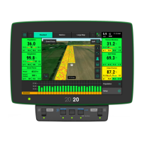
Bus Assignment - Select each CAN network and
assign the total number of SRM backbone
connectors that are being used on that network.
Total SRM Backbone Connectors include all the
connectors where an SRM or BXM is installed.
Repeat this for each CAN Bus Network.
Refer to Appendix B (Tower Style) or Appendix
C (CCS/Box Drill Style) for charting correct
module assignments.
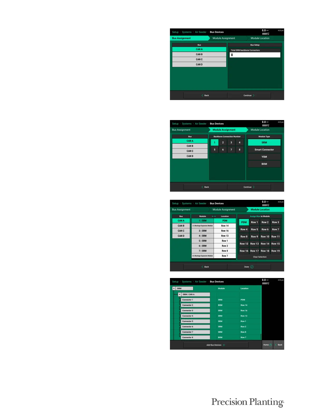
Module Assignment – For each backbone
connection, select the module type present.
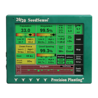
Module Location – Assign each module a
location; for each CAN network, select each
module and assign a row..
Note: The first module on CAN A must always
be the PDM.
Bus Devices Overview — Once all the modules
are assigned, the Bus Devices Overview page
shows all of the assigned modules in order. This
chart should match Appendix B or C when
finished.