Operational Specifications 10
Copyright © profichip GmbH, 2012
10.6 Timing Characteristics
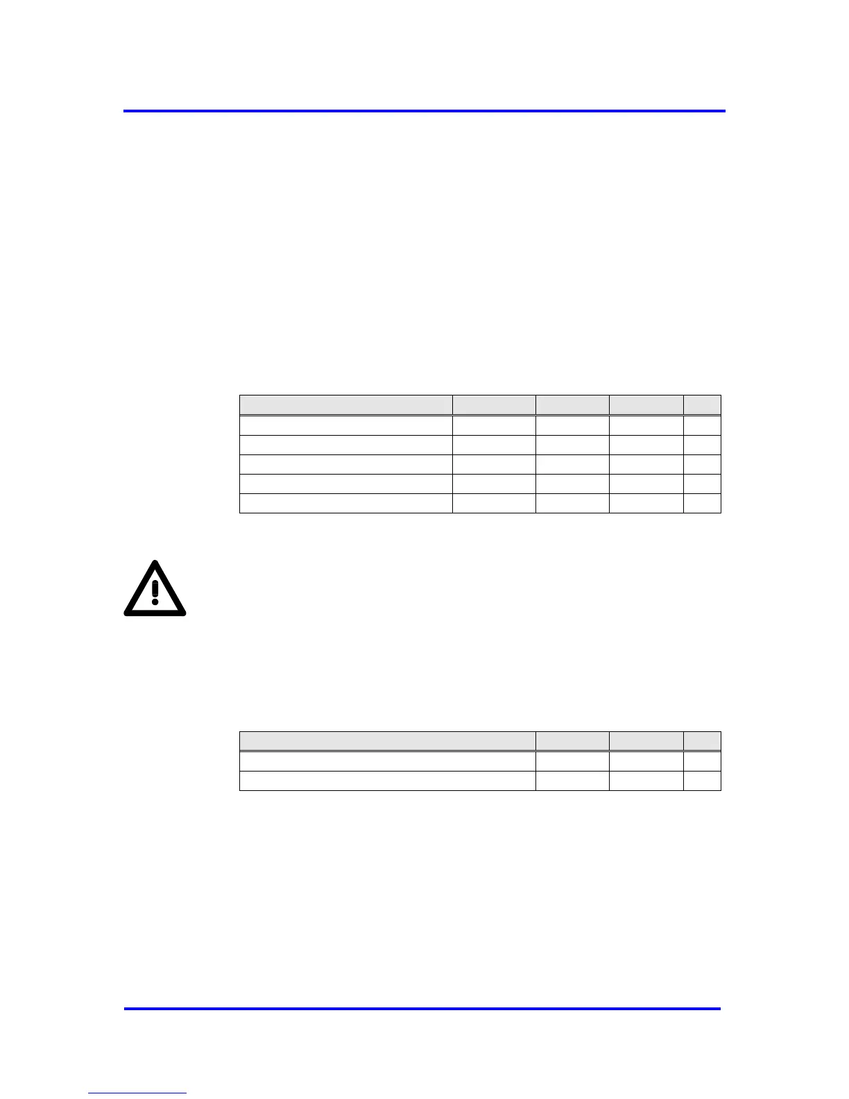
All signals beginning with ‘X’ are ‘low active’. All timing values are based on
the capacitive loads specified in the table above.
10.6.1 System Bus Interface
Clock
Clock frequency is 48 MHz. Distortion of the clock signal is permissible up
to a ratio of 30:70 at the threshold levels 0.9 V and 2.1 V.
Figure 10-6: Clock Timing
Note:
The VPC3+S is equipped with 5V tolerant inputs.
Interrupt:
After acknowledging an interrupt with EOI, the interrupt output of the
VPC3+S is deactivated for at least 1 us or 1 ms depending on the bit
EOI_Time_Base in Mode Register 0.
Interrupt inactive time EOI_Timebase = ‘0’
Interrupt inactive time EOI_Timebase = ‘1’
Figure 10-7: End-of-Interrupt Timing
Reset:
VPC3+S requires a minimum reset phase of 100 ns at power-on.