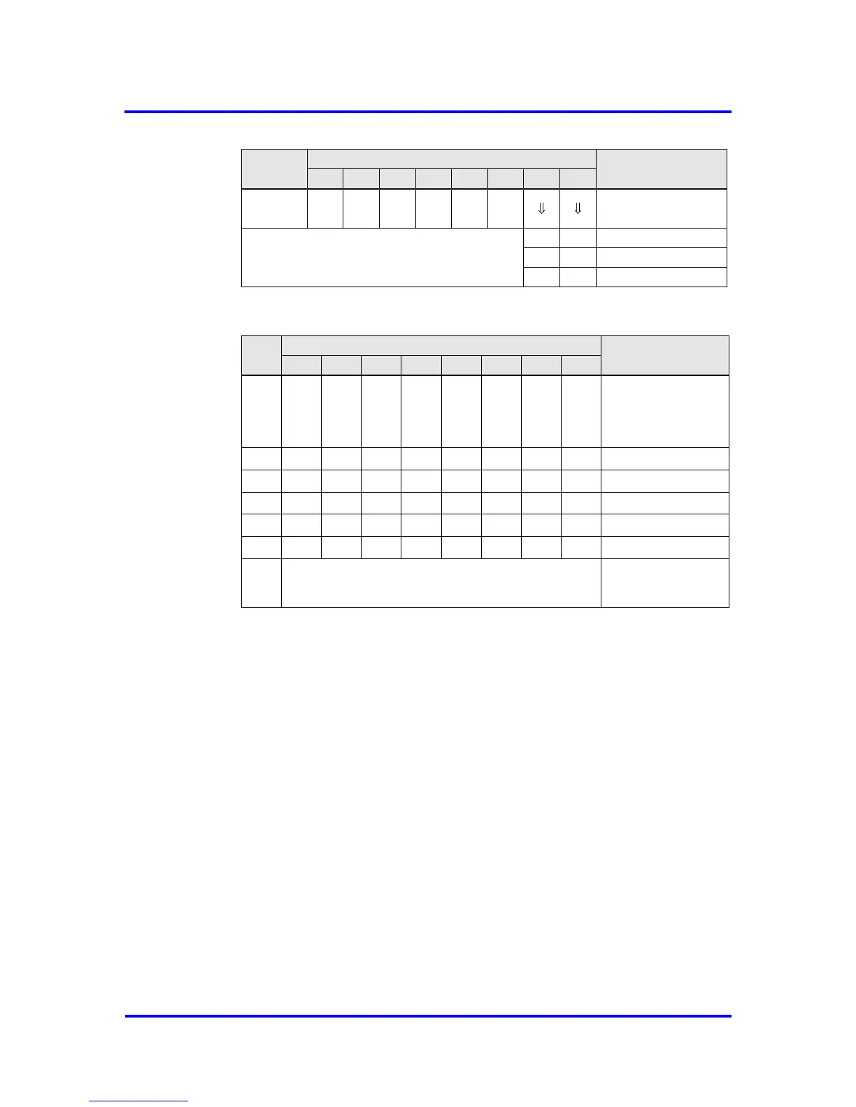
Figure 6-11: Format of the Diagnosis-Buffer
The Ext_Diag_Data must be entered into the buffers after the VPC3+S
internal diagnosis data. Three different formats are possible here: device-
related, ID-related and port-related. If PROFIBUS DP extensions shall be
used, the device-related diagnosis is substituted by alarm and status
messages. In addition to the Ext_Diag_Data, the buffer length also includes
the VPC3+S diagnosis bytes (R_Len_Diag_Buf 1, R_Len_Diag_Buf 2).
6.2.5 Write_Read_Data / Data_Exchange (Default_SAP)
Writing Outputs
The VPC3+S writes the received output data in the 'D' buffer. After an error-
free receipt, the VPC3+S shifts the newly filled buffer from ‘D’ to ‘N'. In
addition, the DX_Out interrupt is generated. The user now fetches the
current output data from ‘N’. The buffer changes from ‘N’ to ‘U’ with the
Next_Dout_Buffer_Cmd, so that the current data can be transmitted to the
application by a RD_Output request from a DP-Master.