EasyManua.ls Logo

Profichip VPC3+S - Watchdog Timer

Default Icon
132 pages
Print Icon
To Next Page IconTo Next Page
To Previous Page IconTo Previous Page
Loading...
5 ASIC Interface
38
Revision 1.04
VPC3+S User Manual
Copyright © profichip GmbH, 2012
5.3.2 Interrupt Acknowledge / Mask Register
The other interrupt controller registers are assigned in the bit positions like
the Interrupt Request Register.
Address
Register
Reset state
Assignment
02H / 03H
Interrupt
Register (IR)
Readable only
All bits
cleared
04H / 05H
Interrupt
Mask
Register
(IMR)
Writeable, can
be changed
during operation
All bits set
1 = Mask is set and the
interrupt is disabled
0 = Mask is cleared and the
interrupt is enabled
02H / 03H
Interrupt
Acknowledge
Register
(IAR)
Writeable, can
be changed
during operation
All bits
cleared
1 = Interrupt is
acknowledged and the IRR
bit is cleared
0 = IRR bit remains
unchanged
Figure 5-11: Interrupt Acknowledge / Mask Register
The New_(Ext_)Prm_Data, New_Cfg_Data interrupts cannot be
acknowledged via the Interrupt Acknowledge Register. The relevant state
machines clear these interrupts through the user acknowledgements (for
example, User_Prm_Data_Okay etc.).
5.4 Watchdog Timer
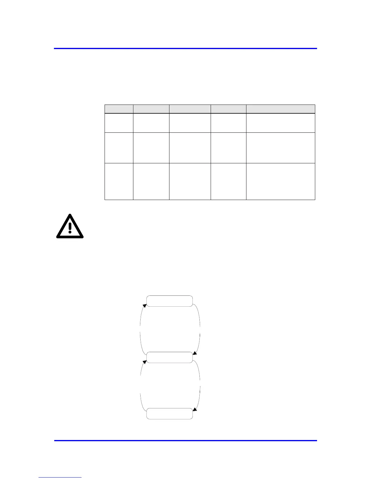
The VPC3+S is able to identify the baud rate automatically. The state ma-
chine is in the BAUD_SEARCH state after each RESET and also after the
Watchdog (WD) Timer has expired in the BAUD_CONTROL state.
BAUD_CONTROL
DP_CONTROL
BAUD_SEARCH
WD_Timeout
baudrate detected
WD_On = 1
WD_On = 0
or
WD_DP_CONTROL_Timeout
Figure 5-12: Watchdog State Machine (WD_SM)

Table of Contents

Other manuals for Profichip VPC3+S