Copyright © profichip GmbH, 2012
5 ASIC Interface
5.1 Mode Registers
In the VPC3+S parameter bits that access the controller directly or which
the controller directly sets are combined in three Mode Registers (0, 1, 2
and 3).
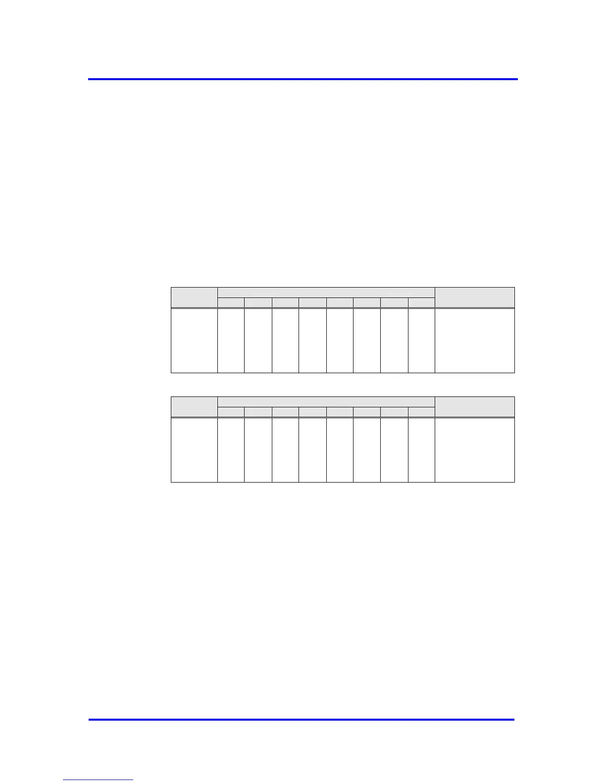
5.1.1 Mode Register 0
Setting parameters for Mode Register 0 may take place in the Offline
state only (for example, after power-on). The VPC3+S may not exit the
Offline state until Mode Register 0, all Control and Organizational
Parameters are loaded (START_VPC3 = 1 in Mode Register 1).
*) If Spec_Clear_Mode = 1 (Fail Safe Mode) the VPC3+S will accept Data_Exchange
telegrams without any output data (data unit length = 0) in the state DATA-EXCH. The
reaction to the outputs can be parameterized in the parameterization telegram.
**) When a large number of parameters have to be transmitted from the DP-Master to the
DP-Slave, the Aux-Buffer 1/2 must have the same length as the Parameter-Buffer.
Sometimes this could reach the limit of the available memory in the VPC3+S. When
Spec_Prm_Buf_Mode = 1 the parameterization data are processed directly in this special
buffer and the Aux-Buffers can be held compact.