Copyright © profichip GmbH, 2012
In order to use Sync and Freeze, these functions must be enabled in the
Mode Register 0.
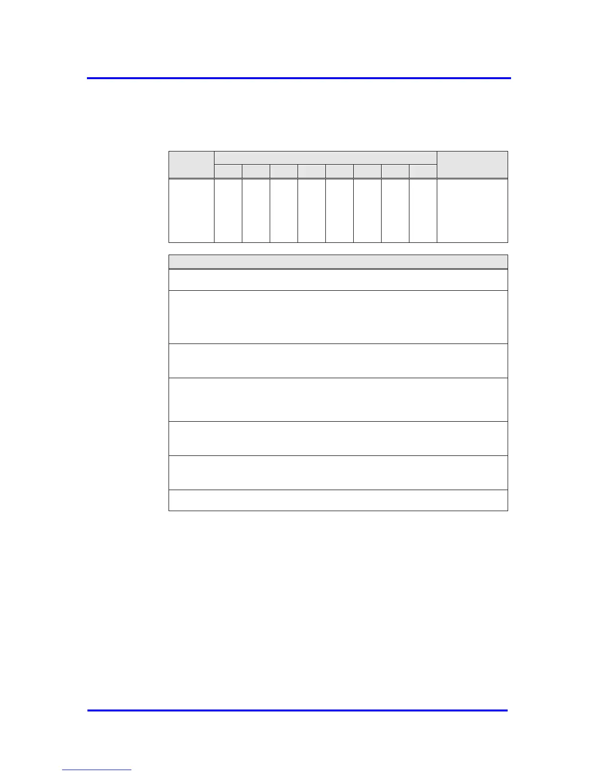
R_GC_
Command
See below
for coding
R_GC_Command, Address 3CH:
Sync:
The output data transferred with a Data_Exchange telegram is changed from ‘D’
to ‘N’. The following transferred output data is kept in ‘D’ until the next Sync
command is given.
Unsync:
The Unsync command cancels the Sync command.
Freeze:
The input data is fetched from ‘N’ to ‘D’ and „frozen“. New input data is not
fetched again until the DP-Master sends the next Freeze command.
Unfreeze:
The Unfreeze command cancels the Freeze command.
Clear_Data:
With this command, the output data is deleted in ‘D’ and is changed to ‘N’.
Figure 6-16: Format of the Global_Control Telegram
6.2.7 RD_Input (SAP 56)
The VPC3+S fetches the input data like it does for the Data_Exchange
telegram. Prior to sending, ‘N’ is shifted to ‘D', if new input data are
available in ‘N'. For ‘Diag.Freeze_Mode = 1', there is no buffer change.
6.2.8 RD_Output (SAP 57)
The VPC3+S fetches the output data from the Dout_Buffer in ‘U’. The user
must preset the output data with ‘0’ during start-up so that no invalid data
can be sent here. If there is a buffer change from ‘N’ to ‘U’ (through the