Copyright © profichip GmbH, 2012
5.1.4 Mode Register 3
Setting parameters for Mode Register 3 may take place in the Offline
State only (like Mode Register 0).
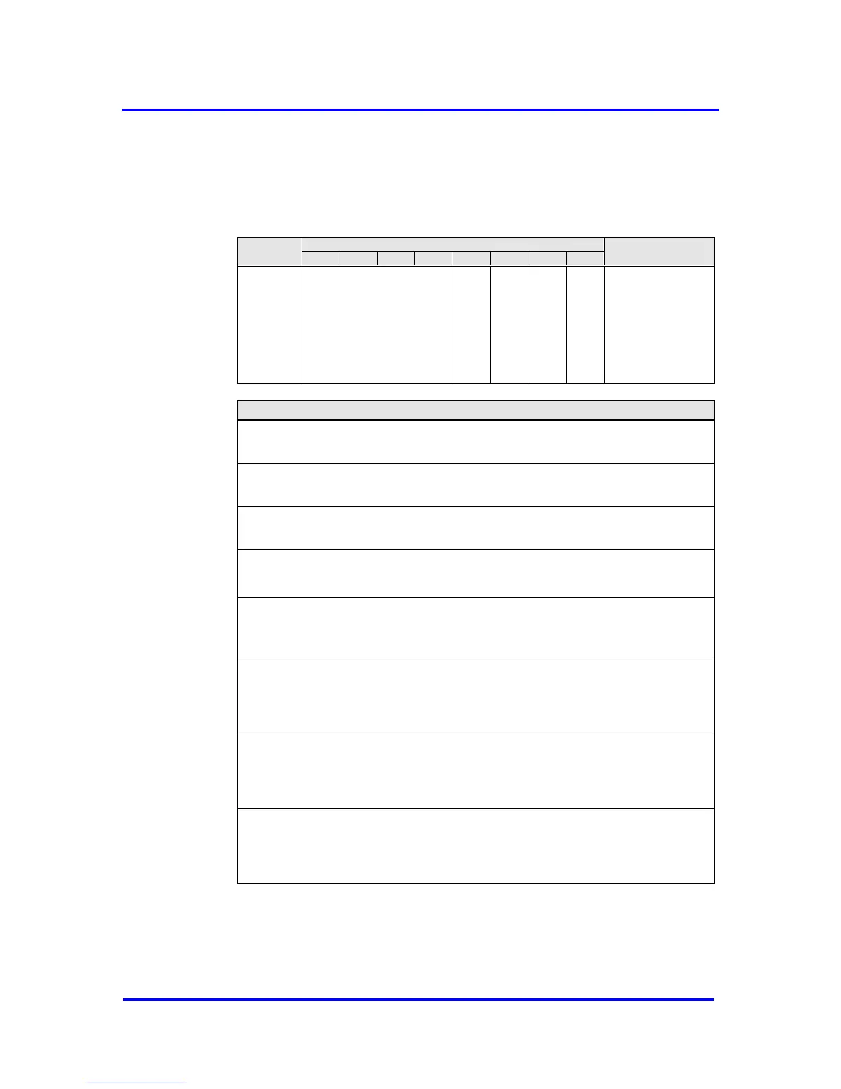
Mode Register 3, Address 12H:
PLL_Supported: Enables IsoM-PLL
0 = PLL is disabled
1 = PLL is enabled; For use of PLL, SYNC_Ena must be set.
En_Chk_SSAP: Evaluation of Source Address Extension
0 = VPC3+ accept any value of S_SAP
1 = VPC3+ only process the received telegram if the S_SAP match to the
default values presented by the IEC 61158
DX_Int_Mode_2: Mode of DX_out interrupt
0 = DX_Out interrupt is generated after each Data_Exch telegram
1 = DX_Out interrupt is only generated, if received data is not equal to current
data in DX_Out buffer of user
GC_Int_Mode_Ext: extend GC_Int_Mode, works only if GC_Int_Mode=0
0 = GC Interrupt is only generated, if changed GC telegram is received
1 = GC Interrupt is only generated, if GC telegram with changed
Control_Command is received
Figure 5-5: Coding of Mode Register 3