Copyright © profichip GmbH, 2012
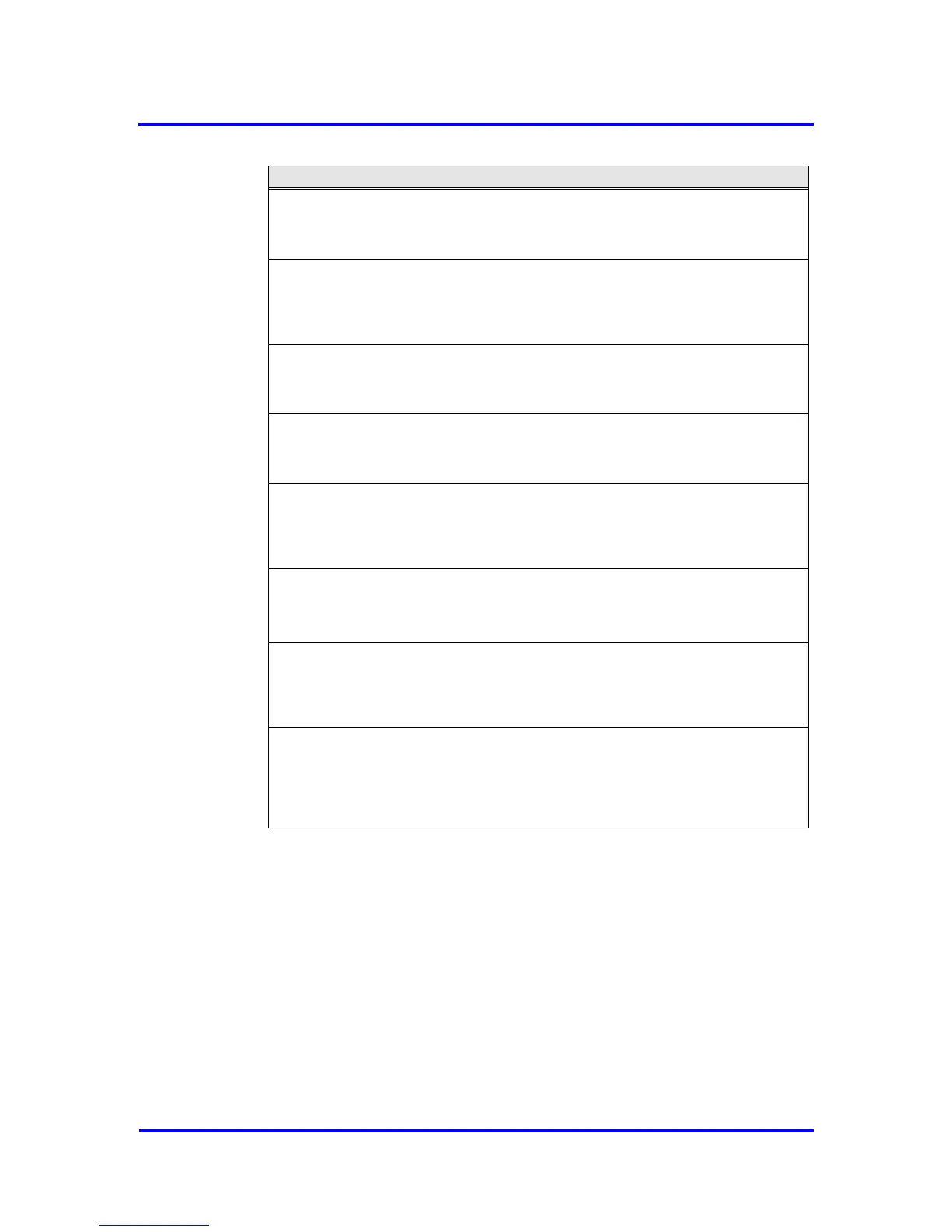
Mode Register 2, Address 0CH:
4KB_Mode: size of internal RAM
0 = 2K Byte RAM (default).
1 = 4K Byte RAM
No_Check_Prm_Reserved: disables checking of the reserved bits in
DPV1_Status_2/3 of Set_Prm telegram
0 = reserved bits of a Set_Prm telegram are checked (default).
1 = reserved bits of a Set_Prm telegram are not checked.
SYNC_Pol: polarity of SYNC pulse (for Isochronous Mode only)
0 = negative polarity of SYNC pulse (default)
1 = positive polarity of SYNC pulse
SYNC_Ena: enables generation of SYNC pulse (for Isochronous Mode only)
0 = SYNC pulse generation is disabled (default)
1 = SYNC pulse generation is enabled
DX_Int_Port: Port mode for DX_Out interrupt (ignored if SYNC_Ena set)
0 = DX_Out interrupt is not assigned to port DATAEXCH (default).
1 = DX_Out Interrupt (synchronized to SYNCH telegram) is assigned to port
DATAEXCH.
DX_Int_Mode: Mode of DX_out interrupt
0 = DX_Out interrupt is only generated, if Len_Dout_Buf is unequal 0 (default).
1 = DX_Out interrupt is generated after every Data_Exchange telegram
No_Check_GC_Reserved: Disables checking of the reserved bits in
Global_Control telegram
0 = reserved bits of a Global_Control telegram are checked (default).
1 = reserved bits of a Global_Control telegram are not checked.
GC_Int_Mode: Controls generation of New_GC_Command interrupt
0 = New_GC_Command interrupt is only generated, if a changed
Global_Control telegram is received
1 = New_GC_Command interrupt is generated after every Global_Control
telegram (default)
Figure 5-4: Coding of Mode Register 2