Copyright © profichip GmbH, 2012
7.3.3 CS (Clock Synchronization)
The Clock Synchronization mechanism synchronizes the time between
devices on a PROFIBUS segment. A time master is a DP-Master. The
scheme used is a “backwards time based correction”. The knowledge of
when a special timer event message was broadcasted is subsequently
used to calculate appropriate clock adjustments.
The synchronized time can be used for time stamp mechanism.
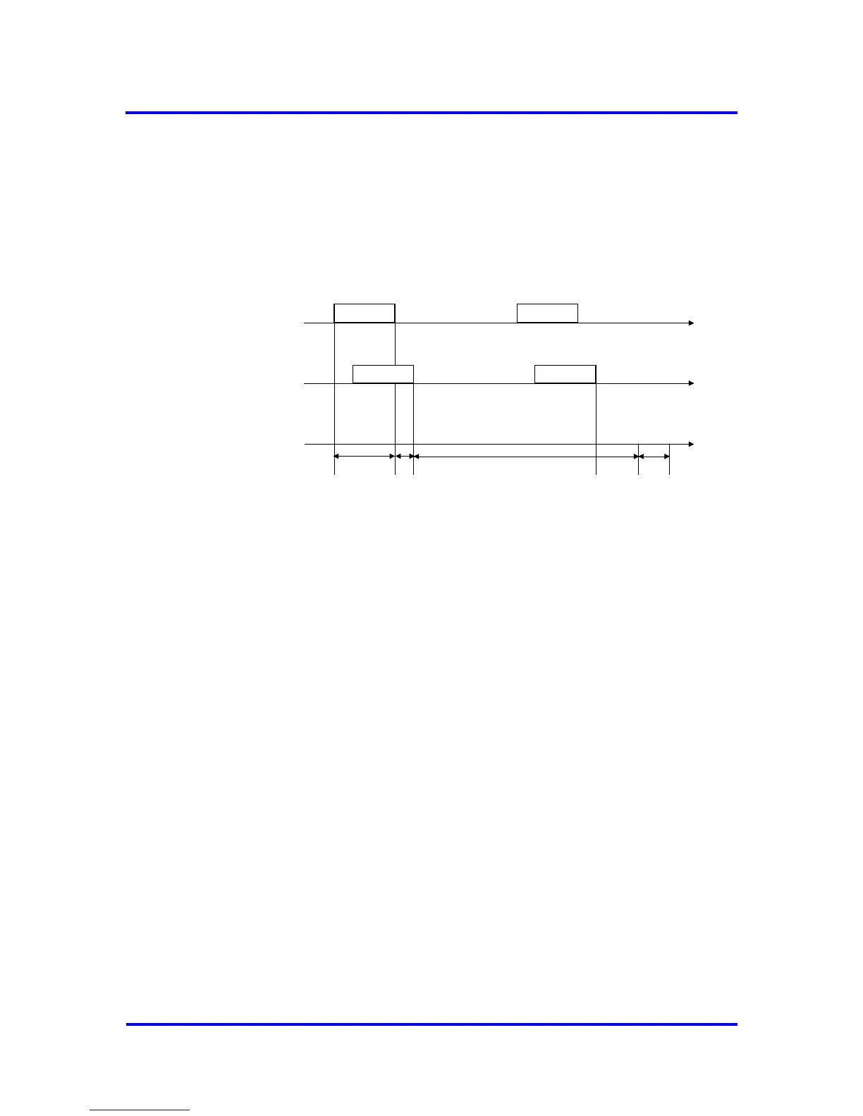
Figure 7-26: clock synchronization mechanism
The clock synchronization sequence consists of two messages broad-
casted by the time master. When the first message, called Time_Event, is
received the VPC3+S starts the receive delay timer (t
RD
). The time master
then sends a second message, called Clock_Value, which contains the
actual time when the Time_Event was sent plus the send delay time (t
SD
).
By receiption of the second message the Clock_Sync interrupt will be
generated. To achieve the most accuracy the receive delay timer is running
until the user reads the Clock_Sync-Buffer.
The VPC3+S only synchronizes the received telegrams, the system time
management is done by the user. The user has also to account for the time
after the receive delay timer has been read till the update of the system
time (t
PD
: process delay time).
The time for transmission delay (t
DT
: CS_Delay_Time) and the
Clock_Sync_Interval are communicated to the VPC3+S by a
Structured_Prm_Data block. The CS_Delay_Time is used by the user to
calculate the system time: t
S
= Clock_Value_Time_Event + t
DT
+ t
RD
+ t
PD