Copyright © profichip GmbH, 2012
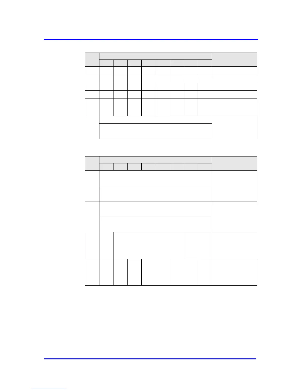
Clock_Sync_Interval
Time Base 10 ms
CS Delay Time
can be omitted
Fraction Part of Seconds (2
31
..0)
Base is 1/(2
32
) Seconds
Figure 7-27: Format of Structured_Prm_Data with Time AR
Seconds (2
31
..0) since 1.1.1900 0:00,00
or since 7.2.2036 6:28:16 if value < 0x9dff4400
Fraction Part of Seconds (2
31
..0)
Base is 1/(2
32
) Seconds
Seconds (2
31
..0) since 1.1.1900 0:00,00
or since 7.2.2036 6:28:16 if value < 0x9dff4400
Fraction Part of Seconds (2
31
..0)
Base is 1/(2
32
) Seconds
Figure 7-28: Format of Clock_Value
Processing Sequence
The Clock_Sync_Interval is a time for monitoring and has to be written into
the Clock_Sync-Buffer by the user. The Time Receiver state machine in the
VPC3+S is started after this write access. The value for
Clock_Sync_Interval is locked until the next LEAVE-MASTER or a new
parameterization occurs. In addition it can be unlocked if the user set the
Stop_Clock_Sync in Command byte.