EasyManua.ls Logo

Profichip VPC3+S - Page 82

Default Icon
132 pages
Print Icon
To Next Page IconTo Next Page
To Previous Page IconTo Previous Page
Loading...
7 PROFIBUS DP Extensions
82
Revision 1.04
VPC3+S User Manual
Copyright © profichip GmbH, 2012
Following to a clock synchronization sequence the Clock_Sync interrupt will
be asserted. Further information is contained in the Status byte. If an
overflow of the Receive_Delay_Timer occurs the Status byte will be
cleared. The VPC3+S cannot write new data to the Clock_Sync-Buffer until
the user has acknowledged the Clock_Sync interrupt. Hence to ensure no
new data overwrites the buffer, the user should read out the buffer before
acknowledging the interrupt.
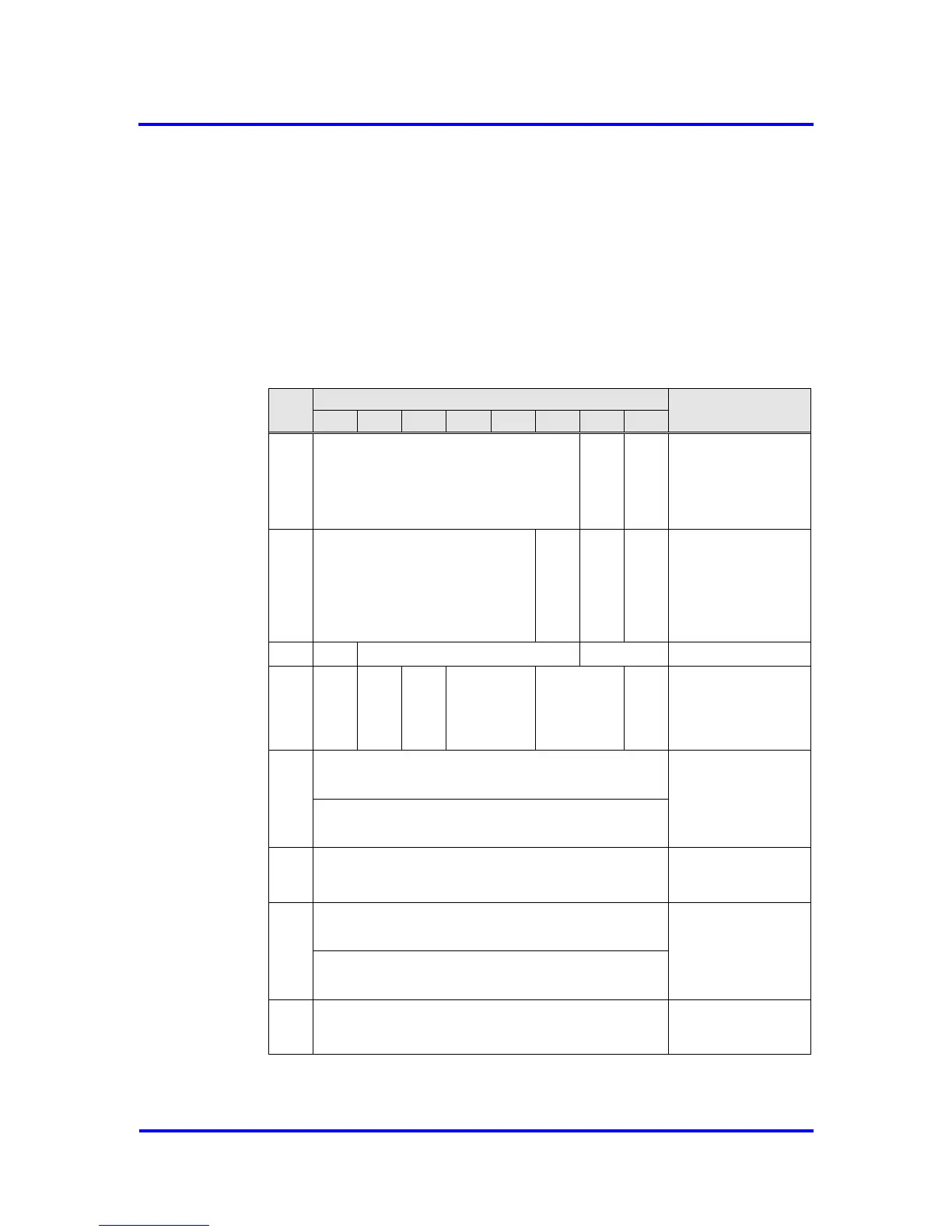
The base address of the Clock_Sync-Buffer depends on the memory mode:
2K Byte mode: 7E0H
4K Byte mode: FE0H
Byte
Bit Position
Designation
7
6
5
4
3
2
1
0
0
reserved
Clock_Sync_
Violation
Set_Time
Status
1
reserved
Clock_Value_
Check_Ena
Ignore_Cyclic_
State_Machine
Stop_
Clock_Sync
Command
2
C
CV
reserved
Clock_Value_Status1
3
ANH
SWT
reserved
CR
reserved
SYF
Clock_Value_Status2
4
:
11
Seconds (2
32
-1 .. 0) since 1.1.1900 0:00,00
or since 7.2.2036 6:28:16 if value < 9DFF4400H
Clock_Value_
Time_Event
Fraction Part of Seconds (2
32
-1 .. 0)
Base is 1/(2
32
) Seconds
12
:
15
(2
32
-1 .. 0)
Time Base 1 μs
Receive_Delay_Time
16
:
23
Seconds (2
32
-1 .. 0) since 1.1.1900 0:00,00
or since 7.2.2036 6:28:16 if value < 9DFF4400H
Clock_Value_
previous_TE
Fraction Part of Seconds (2
32
-1 .. 0)
Base is 1/(2
32
) Seconds
24
:
25
(2
16
-1 .. 0)
Time Base 10 ms
Clock_Sync_Interval

Table of Contents

Other manuals for Profichip VPC3+S