EasyManua.ls Logo

Profichip VPC3+S - Asynchronous Intel Mode

Default Icon
132 pages
Print Icon
To Next Page IconTo Next Page
To Previous Page IconTo Previous Page
Loading...
Pin Description 3
VPC3+S User Manual
Revision 1.04
13
Copyright © profichip GmbH, 2012
The following chapters are describing the different processor interface modes supported by
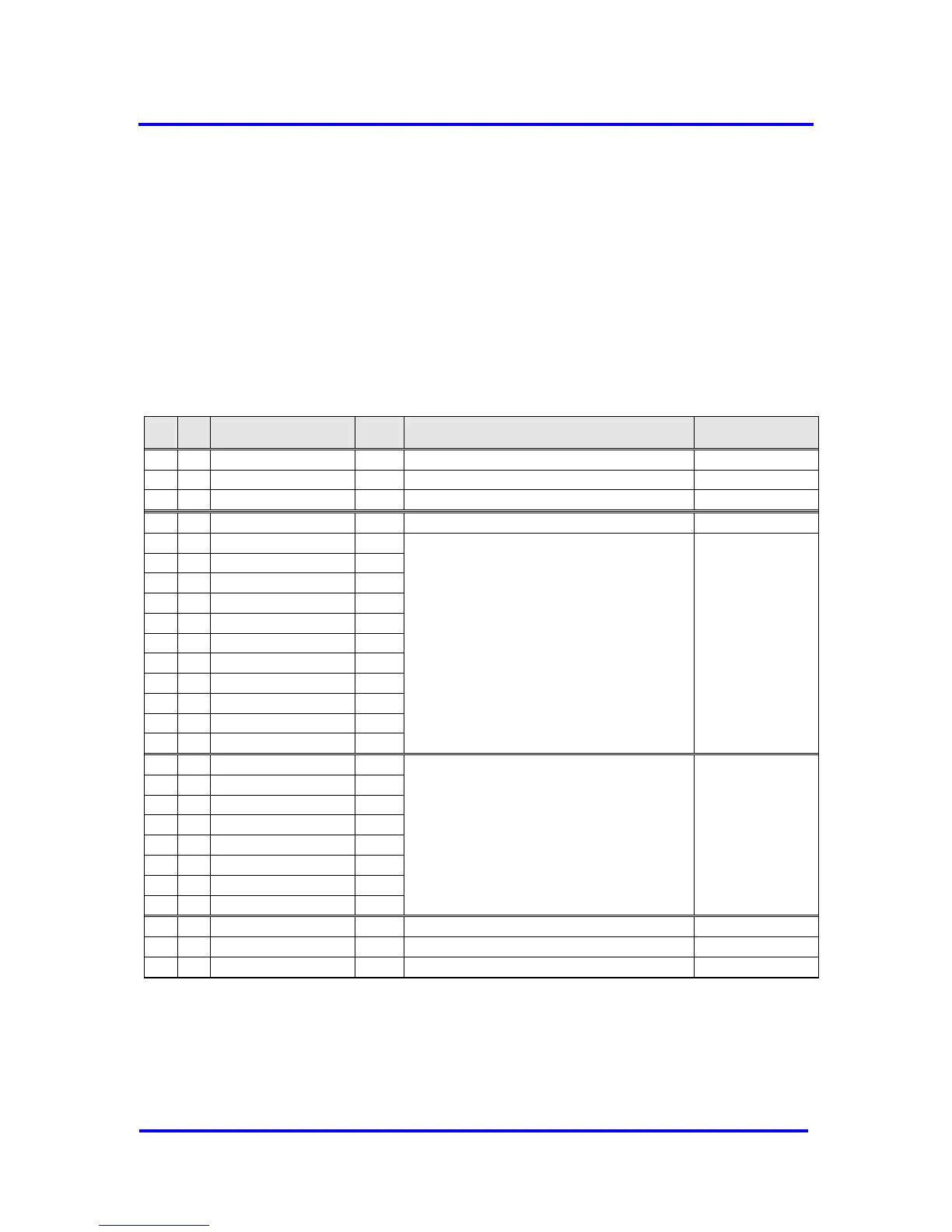
the VPC3+S. For every interface mode the settings of the configuration pins and the signals
necessary to communicate with the microcontroller are listed. Common signals for all
interface types (like clock divider, interrupt and Profibus interface signals are not explicitly
listed in this overview.
3.2.1 Asynchronous Intel Mode
In Asynchronous Intel Mode the data and address busses are separate
(non-multiplexed). Address line 11 is to be connected to pin C5 of the
VPC3+S.
XREADY mechanism is supported.
Ball
BGA
Pin
QFP
In/Out
Description
Connect to
E3
9
I
‘0’: Parallel Interface
GND
E4
28
I
‘0’: Intel Format
GND
D4
33
I
‘0’: Asynchronous Interface Mode
GND
C5
35
I
Address Lines Bit 11
CPU Address Bus 11
C2
2
I
Address Lines Bits [10:0]
CPU
Address Bus [10:0]
B3
44
I
A1
48
I(S)
B1
1
I(S)
C3
45
I
B2
46
I
B4
41
I
A5
38
I
A6
37
I
B5
39
I
B6
36
I
G4
20
IO
Data Bus [7:0]
CPU Data Bus [7:0]
H5
23
IO
H6
24
IO
G5
22
IO
G6
25
IO
F4
21
IO
F6
27
IO
F5
26
IO
C1
3
I
Chip-Select Signal (active low)
CPU Chip-Select
D5
32
I
Write Signal (active low)
CPU Write
C6
34
I
Read Signal (active low)
CPU Read
Figure 3-4: Interface Configuration: Asynchronous Intel Mode

Table of Contents

Other manuals for Profichip VPC3+S