Copyright © profichip GmbH, 2012
Number_of_SYNC:
Number of SYNC cycles per DP cycle:
Number_of_SYNC + 1
Input_Time:
Number of SYNC cycles from start of DP cycle up to T
I
Output_Time:
Number of SYNC cycles from start of DP cycle up to T
O
E_limit:
Number of acceptable synchronization errors during time interval.
Figure 7-23: Format of the PLL_Buffer
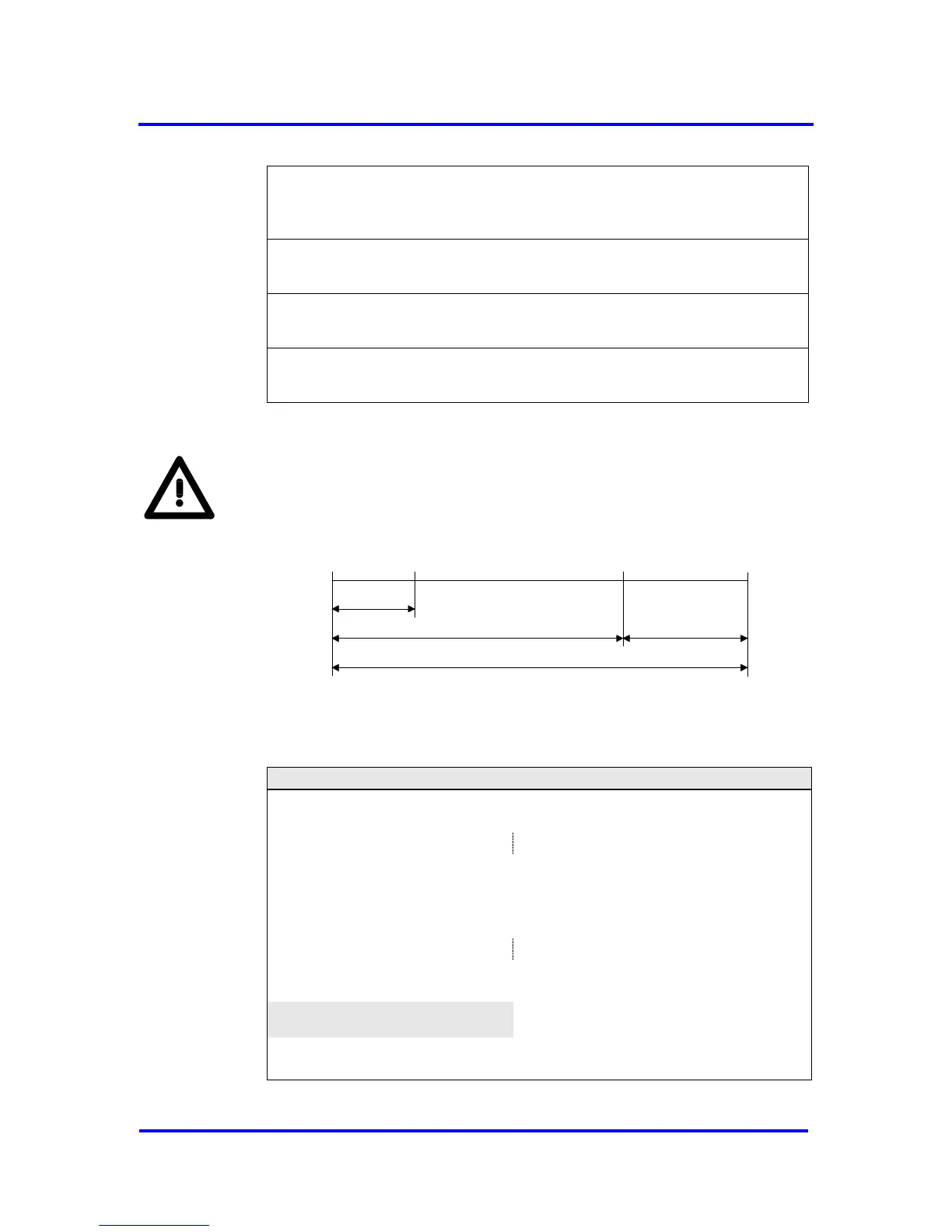
T
I
in the Structured_Prm_Data block is the period of time between
actual value acquisition and the start of new DP cycle whereas T
PLL_I
is
the period of time from the start of DP cycle to the point of data
acquisition.
T
O
; T
PLL_O
T
I
T
PLL_I
T
DP
start of
DP cycle
start of
DP cycle
actual value
acquisition
setpoint
transfer
Figure 7-24: configuration of T
PLL_O
and T
PLL_I
If none of the Enable_xx_Clock bits is set the PLL generates a SYNC clock
after every expiration of the slave application cycle (= T
SYNC
).
configure DP-Slave for IsoM
set PLL_Support
receive Set_(Ext_)Prm
set New_(Ext_)Prm_Data interrupt
acknowledge New_(Ext_)Prm_Data interrupt
configure PLL
synchronization of PLL to GC clock →
set hit display
release clock on SYNC pin
Figure 7-25: Start up of PLL (grey scaled task omitted if SYNC_Mode=0)