Copyright © profichip GmbH, 2012
Data_Exchange with high-priority response data. That signals the DP-
Master that new diagnosis data are present at the DP-Slave. The DP-
Master then fetches the new diagnosis data with a Slave_Diag telegram.
Then the Diag_Flag is cleared again. However, if the user signals
‘Diag.Stat_Diag = 1’ (that is static diagnosis, see the structure of the
Diagnosis-Buffer), the Diag_Flag still remains activated after the relevant
DP-Master has fetched the diagnosis. The user can poll the Diag_Flag in
the Status Register to find out whether the DP-Master has already fetched
the diagnosis data before the old data is exchanged for the new data.
According to IEC 61158, Static Diagnosis should only be used during
start-up.
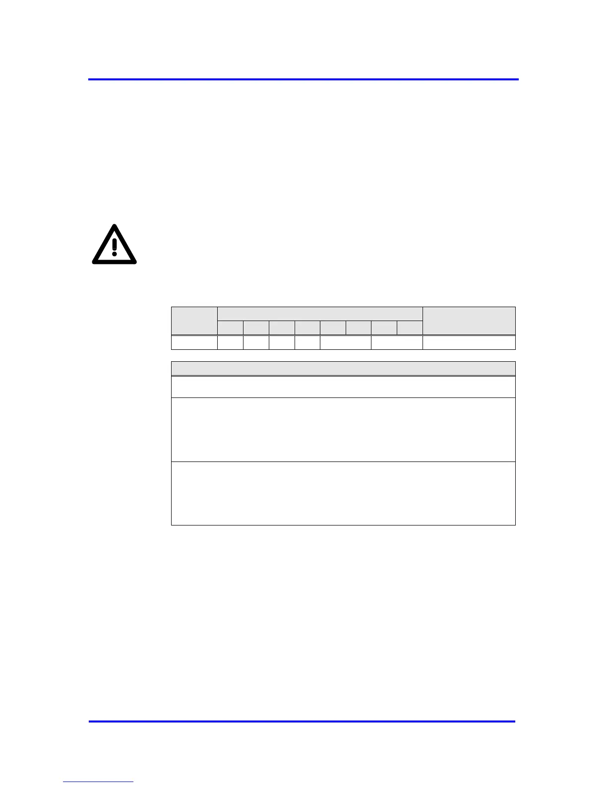
Status coding for the diagnosis buffers is stored in the Diag_Buffer_SM
control parameter. The user can read this cell with the possible codings for
both buffers: User, VPC3+, or VPC3+_Send_Mode.
Figure 6-9: Diagnosis Buffer Assignment
The New_Diag_Cmd is also a read access to a defined control parameter
indicating which Diagnosis-Buffer belongs to the user after the exchange or
whether both buffers are currently assigned to the VPC3+S (No_Buffer,
Diag_Buf1, Diag_Buf2).