Copyright © profichip GmbH, 2012
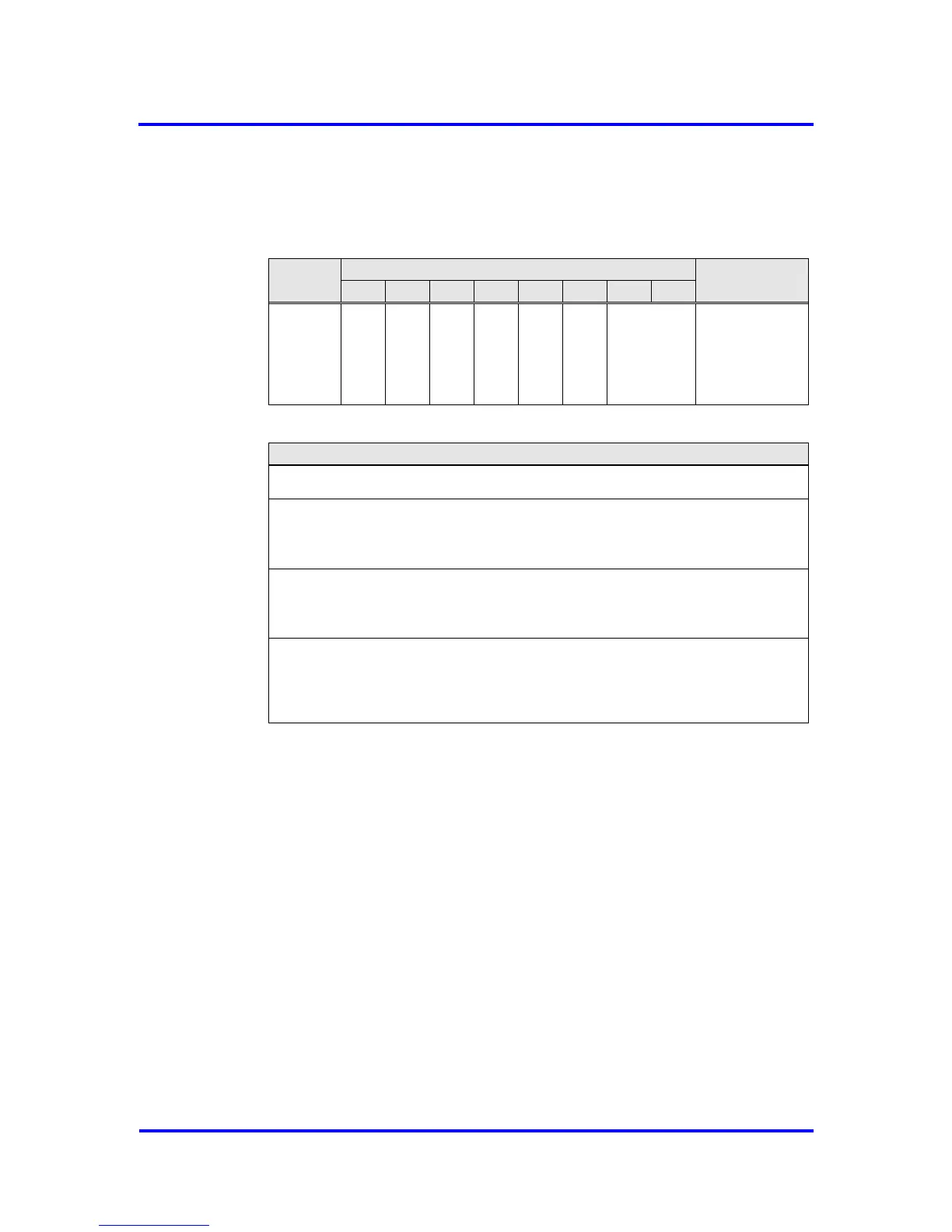
When reading the Next_Dout_Buffer_Cmd the user gets the information
which buffer (‘U’ buffer) belongs to the user after the change, or whether a
change has taken place at all.
Figure 6-13: Coding of Next_Dout_Buf_Cmd
The user must clear the ‘U’ buffer during initialization so that defined
(cleared) data can be sent for a RD_Output telegram before the first data
cycle.
Reading Inputs
The VPC3+S sends the input data from the ‘D’ buffer. Prior to sending, the
VPC3+S fetches the Din-Buffer from ‘N’ to ‘D'. If no new buffer is present in
‘N', there is no change.
The user makes the new data available in ‘U’. With the
New_Din_Buffer_Cmd, the buffer changes from ‘U’ to ‘N’. If the user’s
preparation cycle time is shorter than the bus cycle time, not all new input
data are sent, but just the most current. At a 12 Mbit/s baud rate, it is more
likely, however, that the user’s preparation cycle time is larger than the bus
cycle time. Then the VPC3+S sends the same data several times in
succession.