Copyright © profichip GmbH, 2012
Response_Sent: Response-Buffer sent
0 = no Response sent
1 = Response sent
SAP_Number: 0 – 51
Request_SA: The source address of a request is compared with this value. At
differences, the VPC3+S response with “no service activated” (RS). The default
value for this entry is 7FH.
Request_SSAP: The source SAP of a request is compared with this value. At
differences, the VPC3+S response with “no service activated” (RS). The default
value for this entry is 7FH.
Service_Supported: Indicates the permitted FDL service.
00 = all FDL services allowed
Ind_Buf_Ptr[0]: pointer to Indication-Buffer 0
Ind_Buf_Ptr[1]: pointer to Indication-Buffer 1
Resp_Buf_Ptr: pointer to Response-Buffer
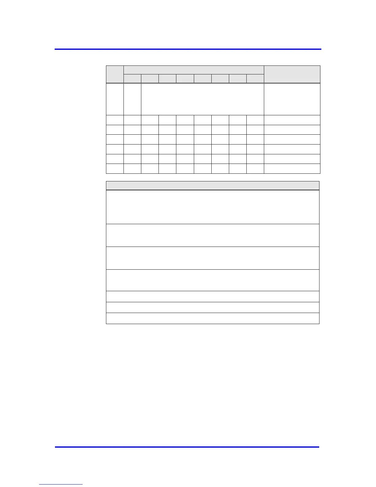
Figure 7-3: SAP-List entry
In addition an Indication- and Response-Buffer are needed. Each buffer
consists of a 4-byte header for the buffer management and a data block of
configurable length.