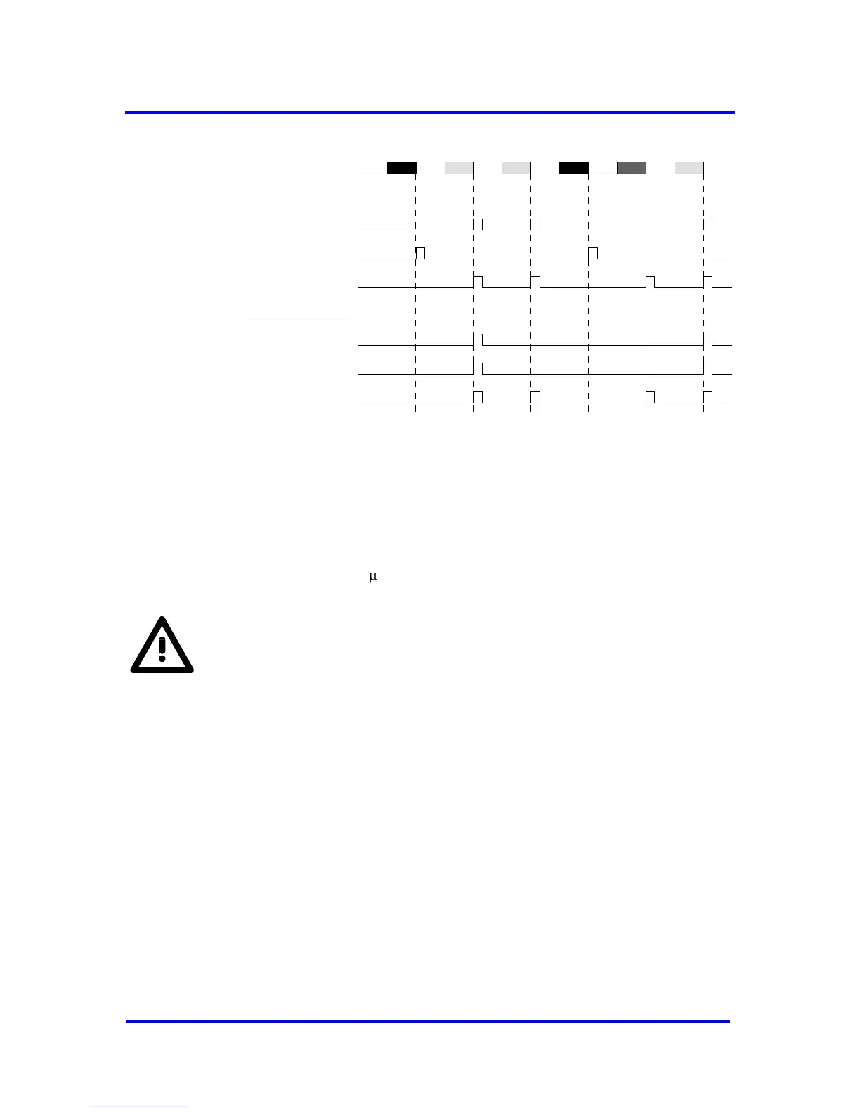
Figure 7-17: SYNC-signal and interrupts for synchronization modes (picture only
shows the effects by reception of telegrams; time between telegrams is not equal)
Isochronous Mode
To enable the Isochronous Mode in the VPC3+S, bit SYNC_Ena in Mode
Register 2 must be set. Additionally the Spec_Clear_Mode in Mode
Register 0 must be set. The polarity of the SYNC signal can be adjusted
with the SYNC_Pol bit. The register Sync_PW contains a multiplicator with
the base of 1/12 s to adjust the SYNC pulse width. Settings in the
Set_Prm telegram are shown below.
The Structured_Prm_Data block IsoM (Structure_Type = 4) is also
required for the application. If it is sent by Set_Prm telegram the bit
Prm_Structure must be set.