Copyright © profichip GmbH, 2012
DP-Slave in an IsoM network
To enable cyclic synchronization via the ‘Simple Sync Mode', the bit
DX_Int_Port in Mode Register 2 has to be set. Bit SYNC_Ena must not be
set. The settings of the pulse polarity are adjusted like described in the
IsoM section.
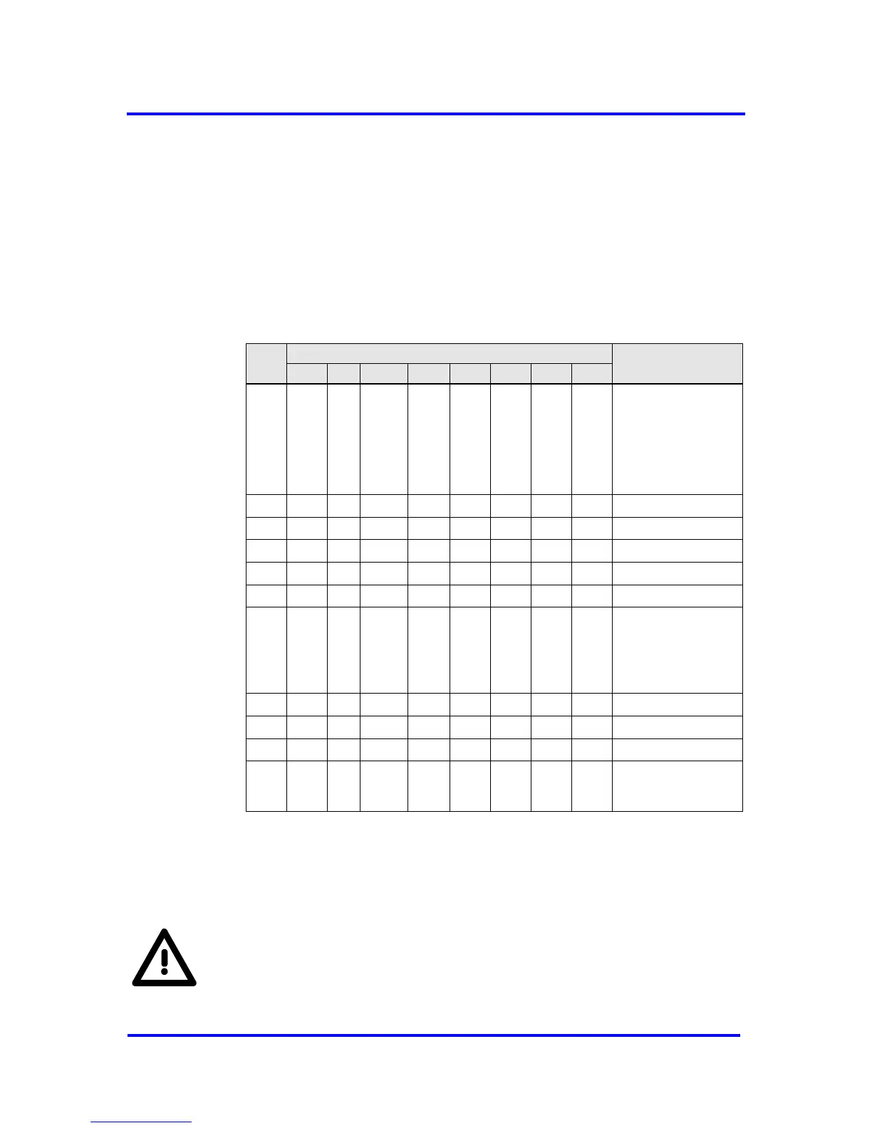
For the parameterization telegram the DP format is used. Though the
DPV1_Status bytes 1-3 could be used as User_Prm_Data, it is generally
recommended starting the User_Prm_Data at byte 10.
Figure 7-19: Format of Set_Prm for DP-Slave using isochronous cycles
In opposite to IsoM the first DX_Out interrupt is generated after the receipt
of a SYNCH telegram. If no Data_Exchange telegram had been received
before a SYNCH occurred, no synchronization signal is generated.
For this mechanism the interrupt controller is used. Hence no signal
will be generated, if the mask for DX_Out in the IMR is set. Since the
synchronization signal is now the DX_Out interrupt, it remains active
until the interrupt is acknowledged.