Copyright © profichip GmbH, 2012
The PLL can be used in Isochronous Mode only (not in Simple Sync
Mode). The user has to take care that the value of SYNC_PW_Reg
matches the SYNC cycle time, which could be smaller than the DP
cycle time now.
If E_limit is reached, a SYNC clock is generated, too.
indicates arriving SYNCH telegram
SYNC clock synchronized to Global_Control clock
enable SYNC clock after successful synchronization
enable only clock0, input or output clock
period of SYNC clock cycle; shall be an integer part
of DP cycle time
ratio of DP cycle to
SYNC cycle (n)
number of SYNC clock cycles per T
DP
number of acceptable synchronization errors
point in time for actual value acquisition
point in time for setpoint transfer
half the width of the tolerance window
start value of PLL window
delay of the generated SYNC clock, to compensate
phase shifts between slaves due to the runtimes of
SYNCH telegram
synchronization errors detected, resynchronization
necessary
PLL is synchronized with the DP-Masters SYNCH
SYNCH telegram arrived within tolerance window
SYNC clock coincides with the (expected)
Global_Control clock
SYNC clock designated for actual value acquisition
SYNC clock designated for setpoint transfer
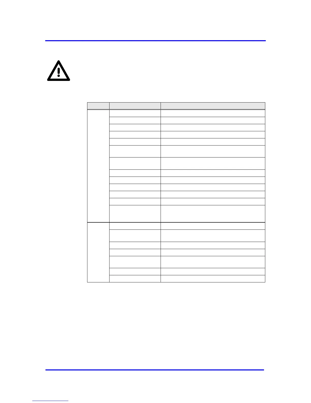
Figure 7-21: Inputs and outputs of the PLL