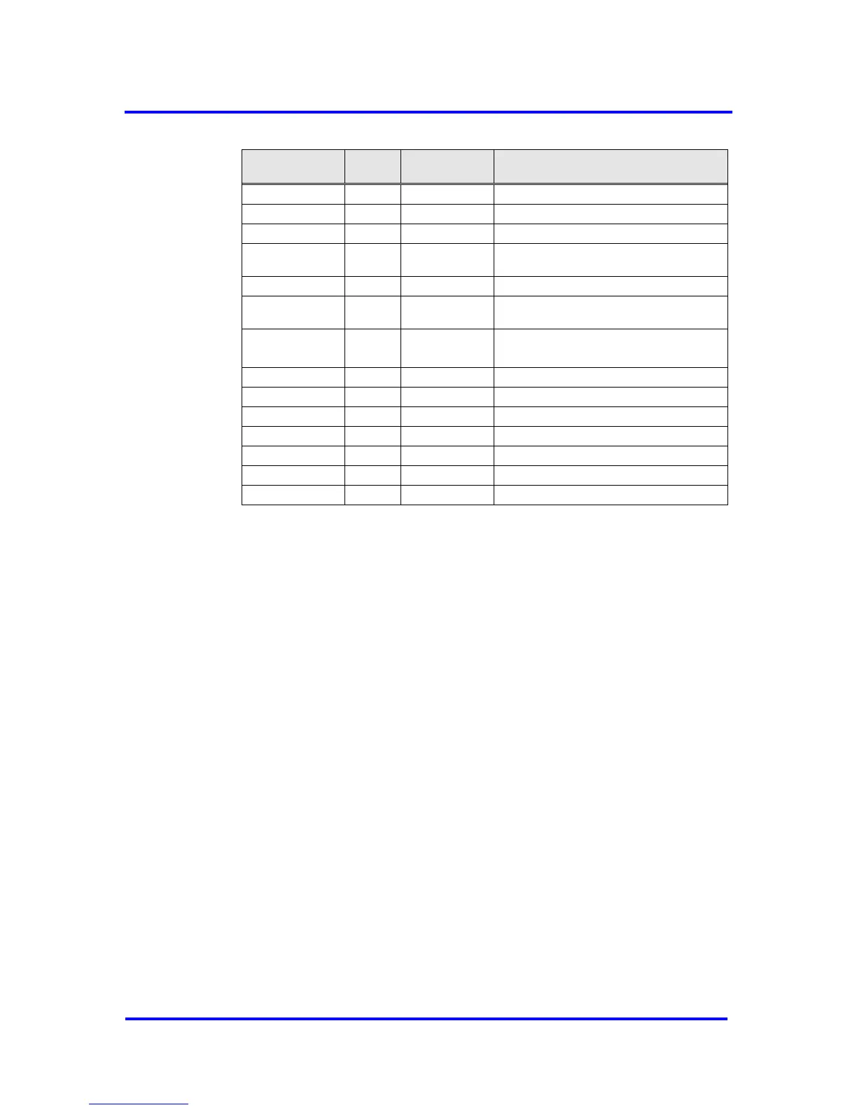
Figure 8-2: Microprocessor Bus Signals
* Due to compatibility reasons to existing competitive chips the XRDY/XDTACK output of the
VPC3+S has push/pull characteristic (no tristate!).
Synchronous Intel Mode
In this mode Intel CPUs like 80C51/52/32 and compatible processor series
from several manufacturers can be used.
Synchronous bus timing without evaluation of the XREADY signal
8-bit multiplexed bus: ADB7..0
The lower address bits AB7..0 are stored with the ALE signal in an in-
ternal address latch.
The internal CS decoder is activated. VPC3+S generates its own CS
signal from the address lines AB10..3. The VPC3+S selects the
relevant address window from the AB2..0 signals.
A11 from the microcontroller must be connected to XCS (pin 1) in 4K
Byte mode as this is the additional address bus signal in this mode. In
2K Byte mode this pin is not used and should be pulled to VDD.
Asynchronous Intel Mode
In this mode various 16-/8-bit microcontroller series like Intel’s x86,
Siemens 80C16x or compatible series from other manufacturers can be
used.
Asynchronous bus timing with evaluation of the XREADY signal
8-bit non-multiplexed bus: DB7..0, AB10..0 (AB11..0 in 4K Byte mode)
The internal VPC3+S address decoder is disabled, the XCS input is
used instead.