ProMinent
®
Page 19
Operation and Settings
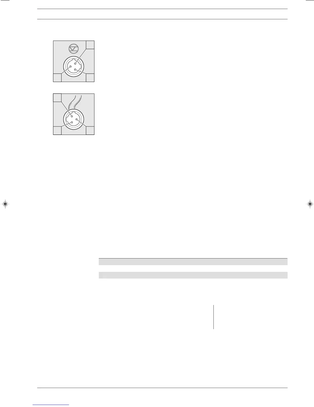
Fig. 09
Fig. 10
Connecting float switch It is possible to fit a two stage float switch to activate early warning and limit switch functions.
Pump configuration
Electrical Interface:
• Open contact voltage: approx. +5 V
• Input resistance: 10 kΩ
• Control: volt free contact (0.5 mA at +5 V).
or: semi conductor switch (residual voltage < 0.7 V)
Plug configuration
Function 3channel cable
pin 1 reference potential (earth) black
pin 2 minimum warning indication blue
pin 3 minimum fault (switches off) brown
Function and fault indicators A signal is sent to the pump (minimum warning or minimum fault) when the liquid level in the
chemical feed tank drops below specific levels.
Three LED displays act as the function and fault indicators.
Green LED indicator, operating display
This LED illuminates briefly when a discharge stroke is activated.
Yellow LED indicator, warning indicator
This LED lights up when the liquid level drops below the first float switch triggering level.
Red LED indicator, fault indicator
This LED lights up when liquid levels reach the fault indicating level (20 mm remaining in chemical
feed tank)
It also flashes to indicate undefined operating status.
Relay
Relay output, fault indicating An alarm relay can be ordered as on option. It switches in case of faults. Whether it drops out or
picks up in case of fault was preselected via the Identcode.
If the alarm relay is refitted, it drops out in case of fault as standard. The relay board is fully
operative after insertion (see section 7.2).
Electrical interface: • Contact load: 250 V/2 A 50/60 Hz
• Operating life: > 200.000 switch functions
VDE cable CSA cable Contact
white white NO (normally open)
green red NC (normally closed)
brown black C (common)
Fault signal output Two semi conductor switches are available to order as signal output and pacing relay.
and pacing signal output These outputs are electrically isolated by optical couplers.
The pulse output of the pump drives an open collector transistor interfaced to the input device.
This option may be retrofitted, the connector cable is plugged in.
Electrical interface: For semi-conductor switch For relay output
• Residual voltage: < 0.4 Volt at I
C
= 1 mA • Contact load:
• Maximum current: < 100 mA 24 V/100 mA 50/60 Hz
• Max. voltage: 24 V DC • Operating life:
• Pacing relay pulse length approx. 100 ms > 200.000 switch functions
BA_BE_021_07_08_GB2.p65 17.07.2008, 14:35 Uhr19