Sensor
Red
Black
Blue
Yellow/Green
Brown
Mains voltage
A1612
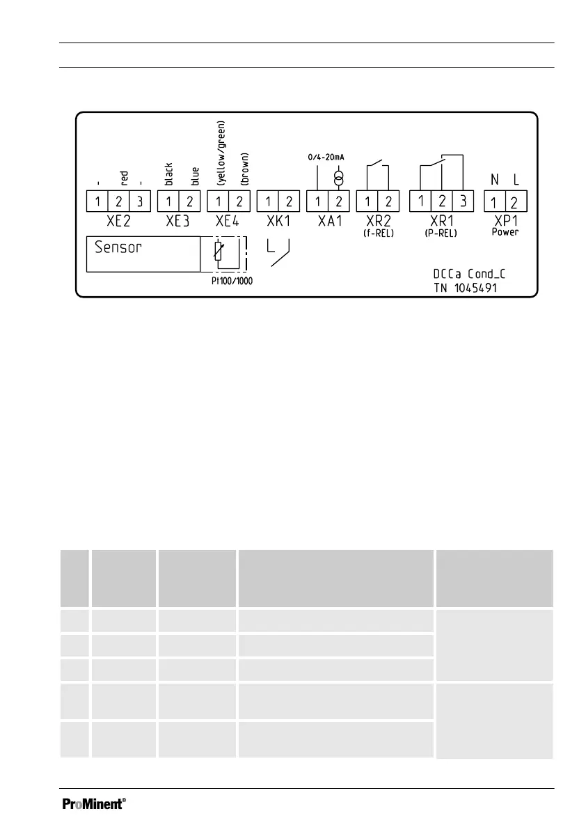
Fig. 12: Terminal diagram label for the Compact Controller (the cable colours relate to the
measuring lines) Ä ‘If you use a sensor without fixed cable or wish to extend the fixed
cable, use the pre-assembled sensor cables.’ on page 40
Red Shielding.
Black Sensor probes, the polarity is
arbitrary.
Blue Sensor probes, the polarity is
arbitrary.
Yellow/
Green
Temperature sensor probes,
the polarity is arbitrary.
Brown Temperature sensor probes,
the polarity is arbitrary.
Table for the terminal diagram, Fig. 13 and/or the terminal diagram label Fig. 12
No. Terminal
Pin
Description Function Terminal type
(Max. diameter/
current)
1 XE2.1 ---- ---- Terminal strip, 3-
pin
(1.5 mm
2
/10 A)
XE2.2
[UREF2 ]
Shield for sensor cable
XE2.3 ---- ----
2 XE3.1
[LFI]
Sensor, 2 probes, the polarity is
arbitrary
Terminal strip, 2-
pin
(1.5 mm
2
/10 A)
XE3.2
[LFGEN]
Sensor, 2 probes, the polarity is
arbitrary
Assembly and installation
33