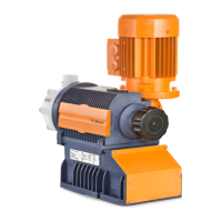
Fig. 4: HMI control elements
1 LCD screen
2 Fault indicator (red)
3 Warning indicator (yellow)
4 Operating indicator (green)
5
[i]
key / Cursor to right
6
[ESC]
key
7
[START/STOP]
key
8
[DOWN]
key
9
[P / OK]
key
10
[UP]
key
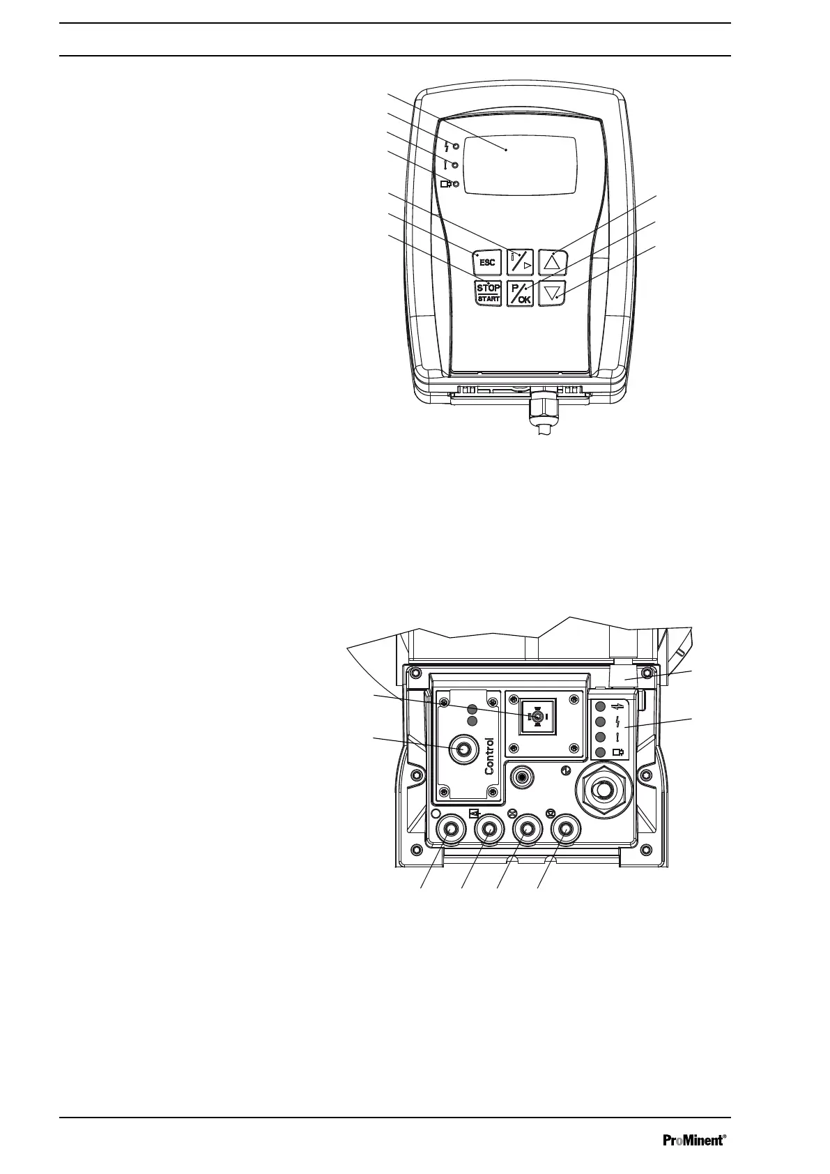
Fig. 5: Connector cover control elements
1 Relay and mA-output (option)
2
Optional module slot (timer, PROFIBUS
®
)
3 "Diaphragm rupture" terminal
4 "External control" terminal
5 "Dosing monitor" terminal
6 "Level Switch" terminal
7 "CAN-bus" port (external)
8 LEDs (as Fig. 4) and status LED CAN bus (external)
not shown Stroke length adjustment wheel
Overview of equipment and control elements
16
 Loading...