MP3
Therapy Beam Analyzer
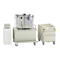
Operating Manual – The Components of the MP3 System
D175.131.00/11 en 13
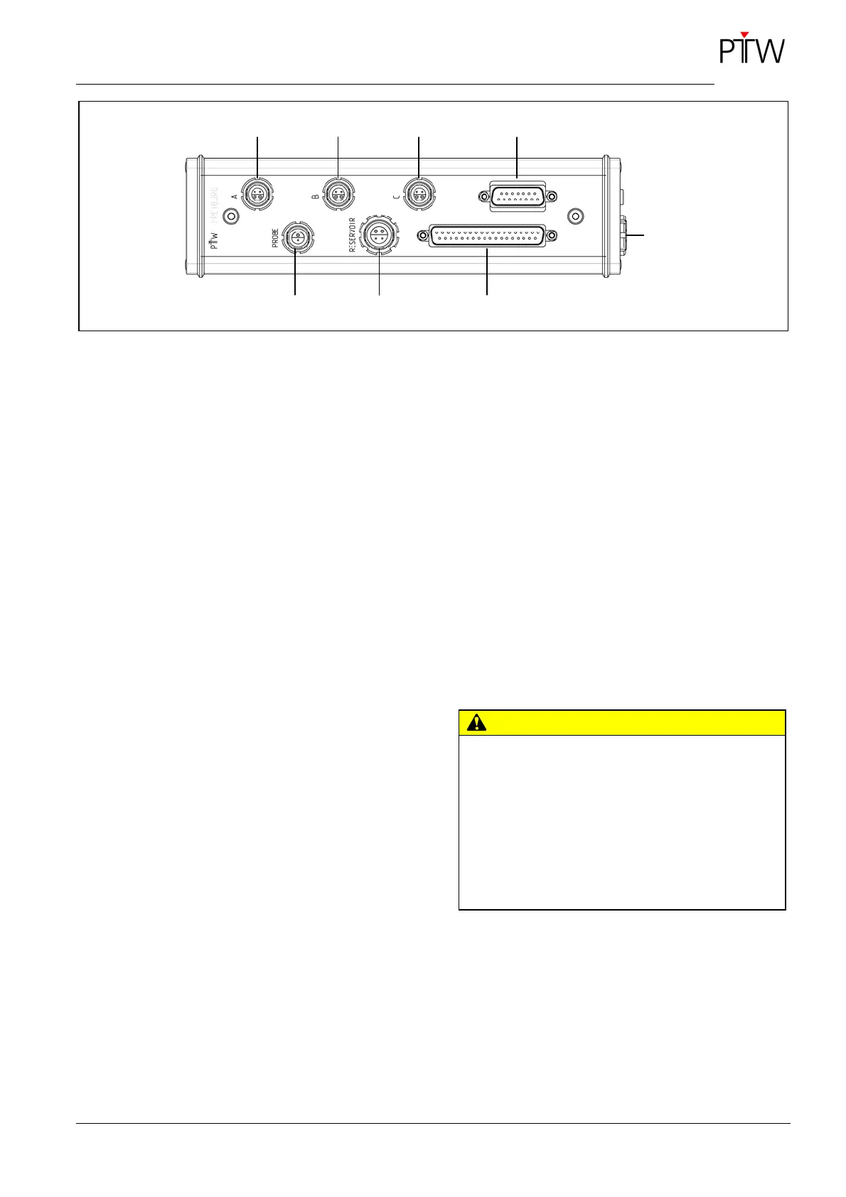
Figure 4: Connections at the junction box
1 Motor cable A
2 Motor cable B
3 Motor cable C
4 Motor cable to the control unit
5 TBA CONTROL PENDANT
6 Control cable to the control unit
7 Water reservoir (only for TPR option)
8 TPR liquid level switch
1.2 Moving Mechanism
The moving mechanism is made of stainless steel
and is permanently installed on the tank. It consists
of three arms with the following designations:
A = horizontal arm, fixed,
B = moving vertical arm and
C = moving horizontal arm.
The moving mechanism is suitable for both horizon-
tal and vertical radiation. Holding devices for detec-
tors to move in the field are screwed to the slider of
the C-arm. The slider and the arms are moved by
stepper motors that permit a minimum step width of
0.1 mm. The reproducibility of the geometric posi-
tioning is also ± 0.1 mm.
The moving range limits can be adjusted for each
axis and stored in the TBA CONTROL UNIT to en-
sure that the detector does not hit the Perspex
walls.
The components of the moving mechanism, particu-
larly the guides and moving parts, are not adversely
affected by water. Bending or contortion due to
water absorption or corrosion is thus excluded.
CAUTION
Improper handling.
Risk of injury!
Do not reach into the Perspex tank while the
moving mechanism is working.
Pay attention that hairs or cloths of the user and
other persons involved do not touch the rotating
spindle.
3
6
2 4 1
5
8
7