MP3
Therapy Beam Analyzer
Operating Manual – Assembly of the System
20 D175.131.00/11 en
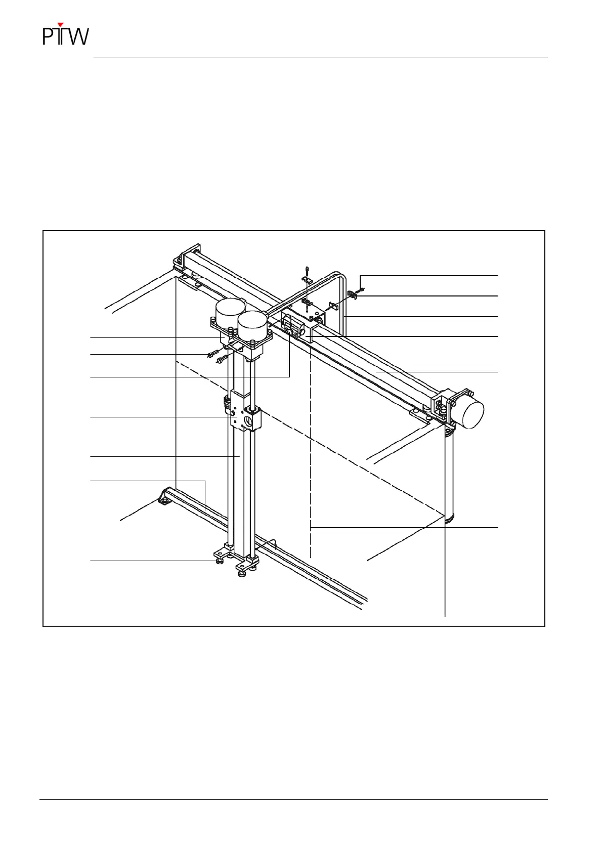
• Hook the B-axis onto the conical bolt of the A-
slide, at the same time guiding the supporting
rolls over the support profile at the bottom of the
Perspex tank, as shown in
Figure 10.
• Mount the B-axis to the A-slider, using two
M5x16 screws. Do not yet tighten the screws.
• Align the B-axis vertically. To do so, use one
edge of guide rail of the B axis and the vertical
crosshair line of the Perspex tank. Now tighten
the two M5x16 screws.
• Remove the M3x12 screws to loosen the cable
holder at the top and back of the A-slider. Se-
cure the two motor cables B/C with the cable
holders and tighten the two M3x12 screws
(
Figure 10).
Figure 10: Mounting the B-axis
1 Gear box B
2 Screw M5x16 DIN 912 (2x)
3 Conical bolt
4 Slider B
5 B-axis
6 Supporting profile
7 Supporting rolls
8 Screw M3x12 DIN 912 (2x)
9 Cable holder
10 Motor cable B/C
11 Slider A
12 A-axis
13 Crosshairs
1
13
4
10
7
2
5
6
3
12
9
8
11