MP3
Therapy Beam Analyzer
Operating Manual – Assembly of the System
D175.131.00/11 en 21
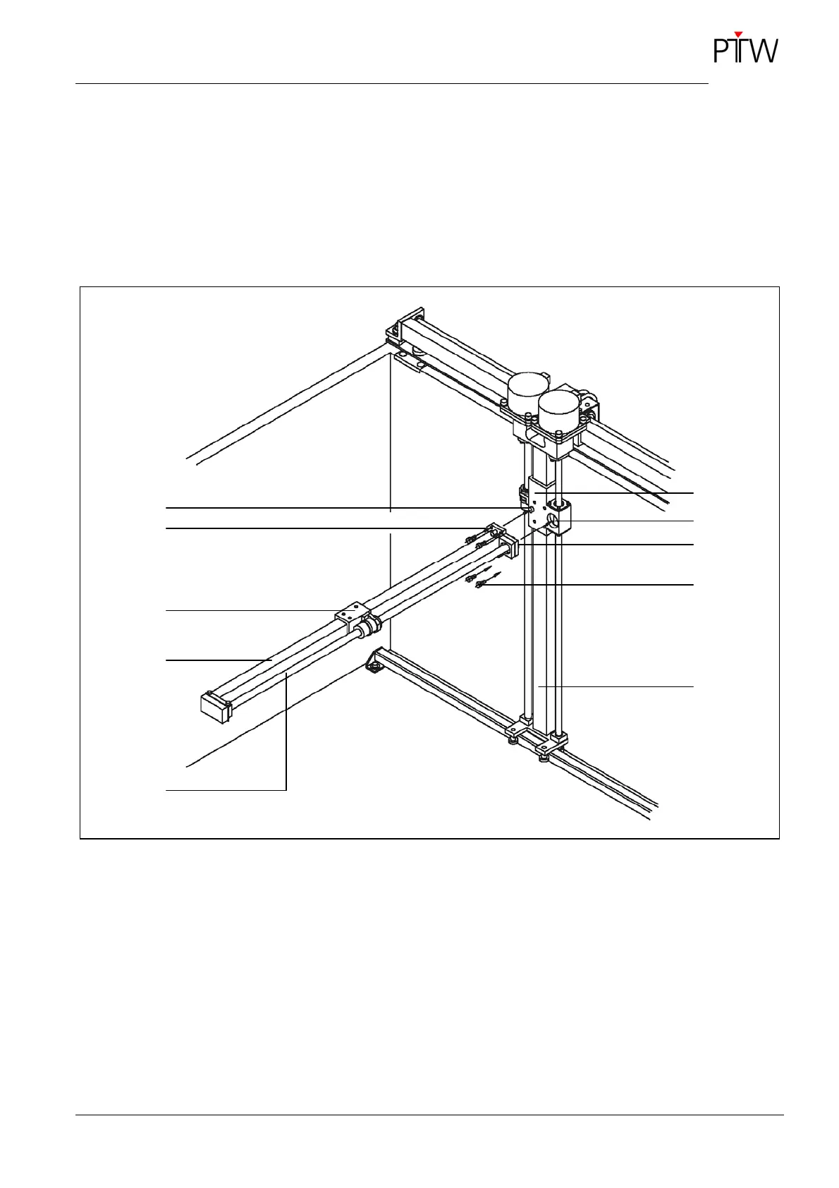
• Place the C-axis on the B-slider, the centering
shoulder engaging in the centering bore and the
catch pin in the groove (
Figure 11).
• Check that the two bevel gear wheels engage
properly in the centering shoulder and adjust, if
necessary; by turning the threaded control shaft
of the C-axis.
• Mount the C-axis to the B-slider, using four
M4x10 screws.
• Plug the three connectors of the motor cables A,
B and C into the corresponding sockets at the
junction box.
Figure 11: Mounting the C-axis
1 Catch pin
2 Groove
3 Slider C
4 Axis C
5 Threaded control shaft
6 Slider B
7 Centering bore
8 Centering shoulder
9 Screw M3x12 DIN 912 (2x)
10 Axis B
3
10
1
7
4
5
8
9
6
2