MITX-DNV0 Series - User Guide, Rev. 1.2
www.quanmax.com
// 30
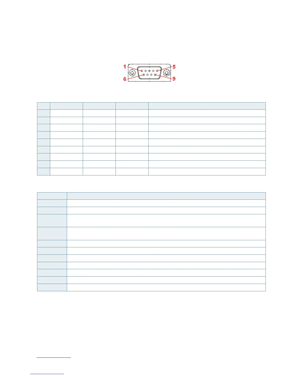
6.4. RS232/422/485 COM1 Connector (CN26)
The external I/O connector panel supports one DB9 RS232/422/485 port.
Figure 9: RS232/422/485 COM1 Connector CN26
Table 15: Pin Assignment RS232/422/485 COM1 Connector CN26
Pin RS232 Signal RS422 Signal RS485 Signal Note
1 DCD TX- DATA-
2 RXD TX+ DATA+
3 TXD RX+ -
4 DTR RX- -
5 GND GND GND
6 DSR - -
7 RTS - -
8 CTS - -
9 RI - -
Table 16: Signal Description
Signal Description
DCD Data Carrier Detect, indicates that the modem or data set has detected the data carrier.
RXD Received Data, receives data from the communications link.
TXD Transmitted Data, sends data to the communications link. The signal is set to the marking state (-12
V) on hardware reset when the transmitter is empty or when loop mode operation is initiated.
DTR Data Terminal Ready, indicates to the modem etc. that the on-board UART is ready to establish
communication link.
GND Power Supply GND signal
DSR Data Set Ready, indicates that the modem etc. is ready to establish a communications link.
RTS Request To Send, indicates to the modem etc. that the on-board UART is ready to exchange data.
CTS Clear To Send, indicates that the modem or data set is ready to exchange data.
RI Ring Indicator, indicates that the modem has received a ringing signal from the telephone line.
TX+/- Transmitted Data differential pair sends data to the communications link.
RX+/- Received Data differential pair receives data from the communications link.
 Loading...