MITX-DNV0 Series - User Guide, Rev. 1.2
www.quanmax.com
// 33
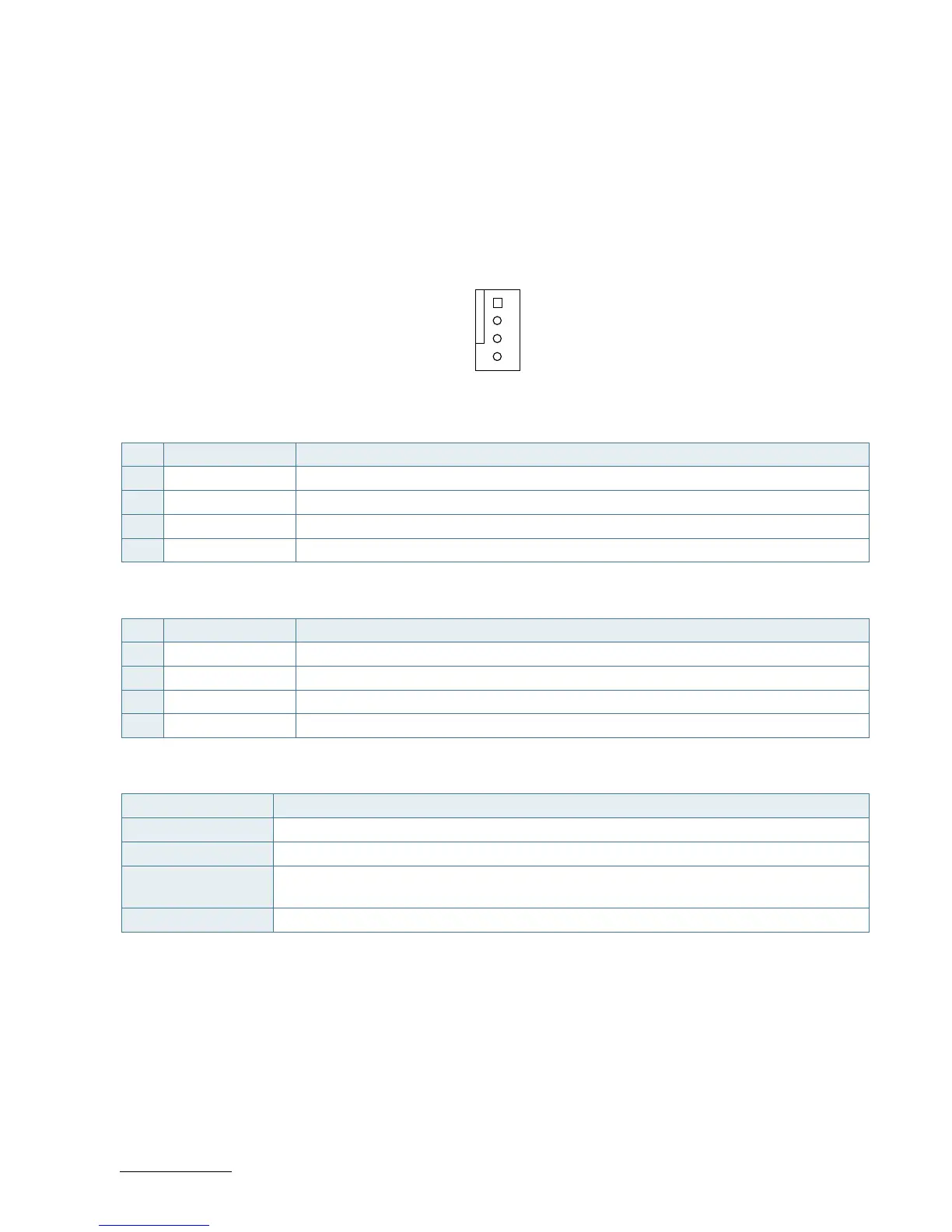
7.2. CPU / System Fan Wafer (FAN1 & FAN2)
The CPU Fan Wafer (FAN1) is used for the connection of the Fan for the CPU. The System Fan Wafer (FAN2) can be
used to power, control and monitor a fan for chassis ventilation etc.
The 4-pin wafer is recommended to be used for driving 4-wire type FAN in order to implement FAN speed control. 3-
wire Fan support is also possible, but no fan speed control is integrated.
Figure 11: CPU / System Fan Wafer FAN1, FAN2
Table 19: 4-Pin Mode FAN1, FAN2
Pin Signal Description
1 GND Ground
2 +12V Power +12V
3 SENSE Sense signal
4 PWM PWM output
Table 20: 3-Pin Mode FAN1, FAN2
Pin Signal Description
1 GND Ground
2 +12V Power +12V
3 SENSE Sense signal
4 - Not used
Table 21: Signal description
Signal Description
GND Power Supply GND signal
+12V +12 V supply for fan
SENSE Sense input signal from the fan, for rotation speed supervision RPM (Rotations Per Minute).
The signal shall be generated by an open collector transistor or similar.
PWM PWM output signal for FAN speed control
 Loading...