MITX-DNV0 Series - User Guide, Rev. 1.2
www.quanmax.com
// 36
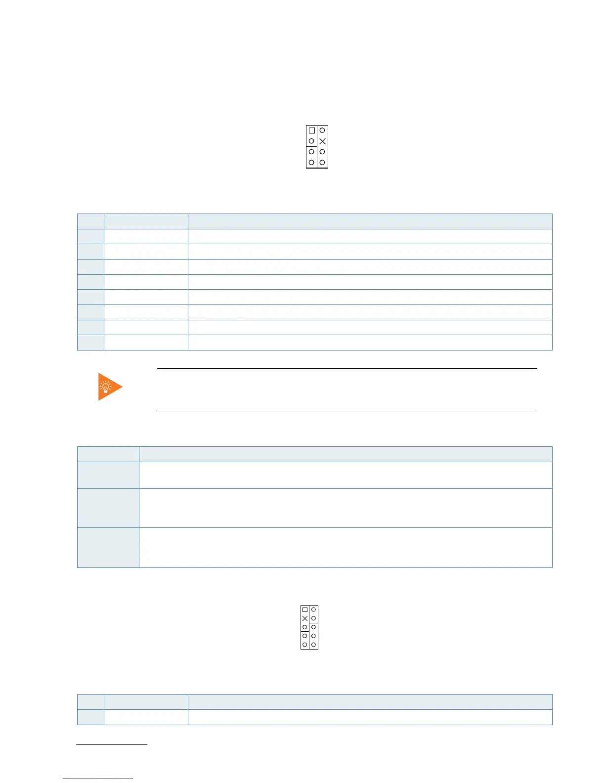
7.5. Front Panel Pin Header (FP1 & FP2)
Figure 14: Front Panel 1 Pin Header FP1
Table 26: Pin Assignment FP1
Pin Signal Note
1 Reset Button +
2 Speaker +
3 Reset Button -
4 NC
5 HDD LED +
6 Internal Speaker -
7 HDD LED -
8 Speaker -
Internal Buzzer is enabled when Pin6-8 is shorted.
Table 27: Signal Description
Signal Description
Reset Button
-/+
Reset Button. This 2-pin connector is for chassis mounted reset button for system reboot without
turning off the system power.
HDD LED -/+ Hard Disk Drive Activity LED. This 2-pin connector is for HDD Activity LED. Connect the HDD Activity
LED cable to this connector. The HDD LED lights up or flashes when data is read from or written to
the HDD.
Internal
Speaker -
Speaker -/+
System warning speaker. The speaker allows user to hear beeps and warnings.
Figure 15: Front Panel 2 Pin Header FP2
Table 28: Pin Assignment FP2
Pin Signal Note
1 Power LED +
 Loading...