CHAPTER 9
92 RCM - Sprayer and AIM Command FLEX™ II Calibration and Operation Manual
NCV COMMUNICATION DIAGNOSTIC TEST
The NCV Communication Test can be used to locate the area of the system to inspect. To run the communication
test:
1. Open the UT Menu and select the RCM - Sprayer Menu button.
2. Select the Diagnostics softkey.
3. Select the Tests tab along the top of the page.
4. Select the NCV Communication Test test in the drown down list.
5. Select the Begin button to start the test. The system will attempt to find CAN Communication Errors on the
NCV CAN bus.
Displayed NCVs are numbered on screen from left to right. These are referenced from the left side of the
machine, facing the normal forward direction of travel.
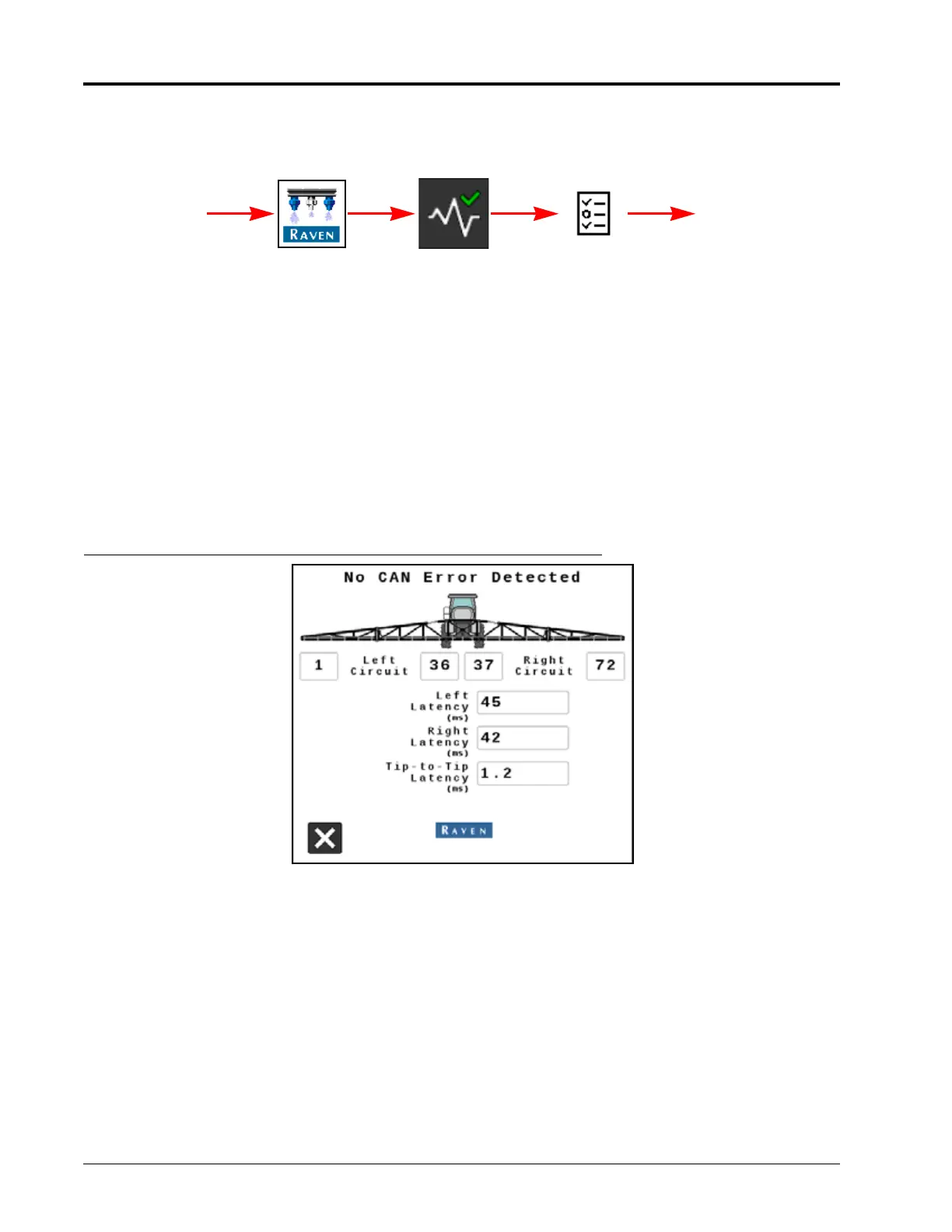
If No CAN Error Detected is displayed, that means that the test has found no detectable communication errors.
Left, right, and tip-to-tip latency times will be displayed
FIGURE 6. NCV Communication Test No CAN Error Detected
If an error occurs, note the "No Communication After NCV” number, and the “Communication Resumes At NCV”
number. The issue is likely between, and possibly includes, these NCVs. Inspect NCVs on the boom, wiring,
connections, or fuses related to the circuit between and including these NCVs.
If there is no communication after the #1 NCV, there may be a power loss between the battery connection and the
NCV cable connections, or a CAN communication problem between the RCM - Sprayer ECU and the NCV cable
connections. Inspect wiring, fuses, and connections before the left and right cable circuit branches.
GENERAL TROUBLESHOOTING
When only a few NCVs are noted, inspect nearby NCVs, connections, pins, and cabling for corrosion, visible
damage, or pinching between those NCVs. In some instances, splices or wiring may be damaged underneath
cable coverings.
RCM - Sprayer Menu Diagnostics
UT Menu
NCV Tests
Tests