APPENDIX C
118 RCM - Sprayer and AIM Command FLEX™ II Calibration and Operation Manual
AIM COMMAND FLEX™ II NOZZLE CONTROL VALVE ASSEMBLY PROCEDURE
To reassemble a nozzle control valve after inspection and maintenance:
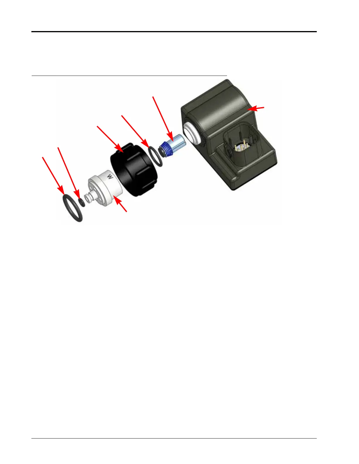
FIGURE 5. Nozzle Control Valve Assembly
1. Replace fly nut (item 3) over valve body (item 4).
2. Replace o-ring (item 2) inside valve body.
3. Place plunger assembly (item 1) into nozzle control valve cavity.
4. Thread the valve body onto the nozzle control valve and finger tighten.
5. Using a valve body removal tool (P/N 321-0000-490), turn valve body 1/4 to 1/3 turn to secure to the valve
body.
6. Verify small o-ring (item 5) is seated into groove on valve body tip.
7. Place large o-ring (item 6) onto valve body face.
8. Thread fly nut onto nozzle body on the spray boom.
9. Hand tighten the fly nut to the nozzle body or use the fly nut wrench if necessary. Do not over tighten.
10. Prior to filling the tank with chemical or starting a field application, refer to the Testing for Leaks section on
page 119 to test the AIM Command FLEX™ II system.
1
2
3
4
5
6
Nozzle
Control Valve